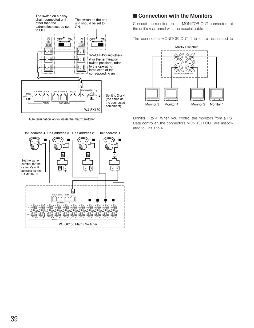
The switch on a daisy-
(A)OFF![]() ON
ON
(B)![]()
![]()
GND
The switch on the end unit should be set to ON.
(A)OFF![]() ON
ON
(B)![]()
![]()
GND
■Connection with the Monitors
Connect the monitors to the MONITOR OUT connectors at the unit's rear panel with the coaxial cable.
The connectors MONITOR OUT 1 to 4 are associated to
Martix Switcher
|
|
|
| ||
|
|
|
| (For the termination | |
|
|
|
| switch positions, refer | |
|
|
|
| to the operating | |
|
|
|
| instruction of the | |
|
|
|
| corresponding unit.) | |
| DATA HDR DATA 4 | DATA 3 DATA 2 | DATA 1 | RS485(CAMERA) |
|
| LINE |
| |||
TERM |
|
|
| ||
|
| 2 SELECT 4 | Set it to 2 or 4 | ||
OFF | ON |
|
| ||
|
|
|
|
| (the same as |
| PS•DATA | RS485(CAMERA) |
|
| the connected |
|
|
|
| equipment). | |
|
|
|
|
| |
Auto termination works inside the matrix switcher.
Unit address 4 Unit address 3 Unit address 2 Unit address 1
Set the same number for the camera's unit address as and
CAMERA IN.
|
| DATA 3 | DATA 2 | DATA 1 |
|
|
|
|
|
|
|
| RS485(CAMERA) |
|
|
|
|
|
|
| |
16 | 10 | 9 | 8 | 7 | 6 | 5 | 4 | 3 | 2 | 1 |
IN |
|
|
|
|
|
|
|
|
|
|
OUT |
|
|
|
|
|
|
|
|
|
|
16 | 10 | 9 | 8 | 7 | 6 | 5 | 4 | 3 | 2 | 1 |
|
| CAMERA |
|
|
|
|
|
|
|
|
31
42 MONITOR OUT
Monitor 3 Monitor 4 | Monitor 2 Monitor 1 |
Monitor 1 to 4. When you control the monitors from a PS· Data controller, the connectors MONITOR OUT are associ- ated to Unit 1 to 4.
39
