●External Equipment Control
When the camera is connected via a receiver, the external equipment connected to the receiver can be controlled.
●Controllable Camera-related Functions
The control is conducted while watching the camera images on the monitor.
•Changing to black and white pictures
•Camera function (Shortcut function)
Note: The specified cameras can control each function. Confirm the functions of the connected cameras and external devices.
Changing to Black and White Pictures
Color images are changeable to black and white images. This function is intended for surveillance in a dark place such as an underground parking lot.
Camera Function (Shortcut Function)
The
Pressing the button can activate the registered functions. Refer to the camera's operating instructions for details on the registered functions.
●Camera Title
The titles for camera identification, which are displayed on the monitor, can be registered.
For example, if a camera setting place is registered as a camera title, operators can be informed where the image is recorded.
The title is displayed in one line.
The available character numbers:
20 (camera number and the characters)
The available characters:
ABCDEFGHIJKLMNOPQRSTUVWXYZabcdefghijkl mnopqrstuvwxyz0123456789!"#$%&'()=+*_:;,. */?
Notes:
•Camera title is configurable in SETUP MENU and WJ- SX150 Administrator Console.
•User font characters can be made through
●Camera Cleaning
When using a combination camera, noise can occur on the monitor after the
In this case, the camera needs to be cleaned.
Camera cleaning is configurable to be conducted at the designated day and time.
The cleaning time is approximately 30 seconds per cam- era.
Notes:
•The images cannot be displayed while cleaning the camera. Use this function when continuous surveillance is not necessary, such as
•Cameras which are operating or being in the sequence mode are not cleaned.
•Camera selection will immediately stop the camera cleaning.
•If noise remains in the monitor even after the camera cleaning, there can be a malfunction. Stop using the camera and consult qualified service personnel.
■Alarm-related Functions
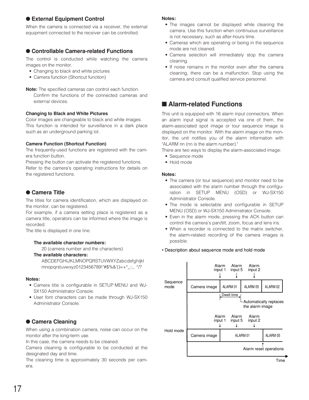
This unit is equipped with 16 alarm input connectors. When an alarm input signal is accepted via one of them, the
There are two ways to display the
•Sequence mode
•Hold mode
Notes:
•The camera (or tour sequence) and monitor need to be associated with the alarm number through the configu- ration in SETUP MENU (OSD) or
•The mode is selectable and configurable in SETUP MENU (OSD) or
•Even in the alarm mode, pressing the ACK button can control the camera's pan/tilt, zoom, focus and lens iris.
•When a recorder is connected to the matrix switcher, the
•Description about sequence mode and hold mode
| Alarm | Alarm | Alarm |
|
|
| |||||||
| input 1 | input 5 | input 2 |
|
|
| |||||||
Sequence |
|
|
|
|
|
|
|
|
|
|
|
|
|
|
|
|
|
|
|
|
|
|
|
|
|
| |
|
|
|
|
|
|
|
|
|
|
|
|
| |
|
|
|
|
|
|
|
|
|
|
|
|
| |
mode | Camera image |
| ALARM 01 |
|
| ALARM 05 |
| ALARM 02 |
| ||||
|
|
|
|
|
|
|
|
|
|
|
| ||
|
|
| Dwell time |
|
| Automatically replaces | |||||||
|
|
|
| ||||||||||
|
|
|
|
|
|
|
|
| |||||
|
|
|
|
|
|
|
|
| |||||
|
|
|
|
|
|
|
|
| |||||
|
|
|
|
|
|
|
|
| the alarm image | ||||
| Alarm | Alarm | Alarm |
|
|
| |||||||
| input 1 | input 5 | input 2 |
|
|
| |||||||
Hold mode |
|
|
|
|
|
|
|
|
|
|
|
|
|
|
|
|
|
|
|
|
|
|
|
|
|
| |
|
|
|
|
|
|
|
|
|
|
|
|
| |
Camera image |
|
| ALARM 01 |
| ALARM 05 | ||||||||
|
|
| |||||||||||
|
|
|
|
|
|
|
|
|
|
|
|
|
|
Alarm reset operations
Time
17
