●Clock
This window configures the unit's clock.
The pattern of the Time & Date box depends on the setting through the Time & Date window.
This picture is the example for U. S. model.
• How to display
To display this window, click on the ![]() (Clock) button in the Time & Date window.
(Clock) button in the Time & Date window.
• Parameters
Time & Date Box: To adjust the clock, click on the ▼ or
▲buttons of Year, Month, Day, Hour and/or Minute
![]() (Put to SX150) button: Changes the unit's clock time into the one which has been configured in this window.
(Put to SX150) button: Changes the unit's clock time into the one which has been configured in this window.
![]() (Cancel Exit) button: Cancels the configuration and closes the Clock window.
(Cancel Exit) button: Cancels the configuration and closes the Clock window.
Note: The clock display pattern is not updated by click-
ing the ![]() (Put to SX150) button in this win- dow. The setup file update will be necessary. (Refer to p. 67 Put a File to SX150.)
(Put to SX150) button in this win- dow. The setup file update will be necessary. (Refer to p. 67 Put a File to SX150.)
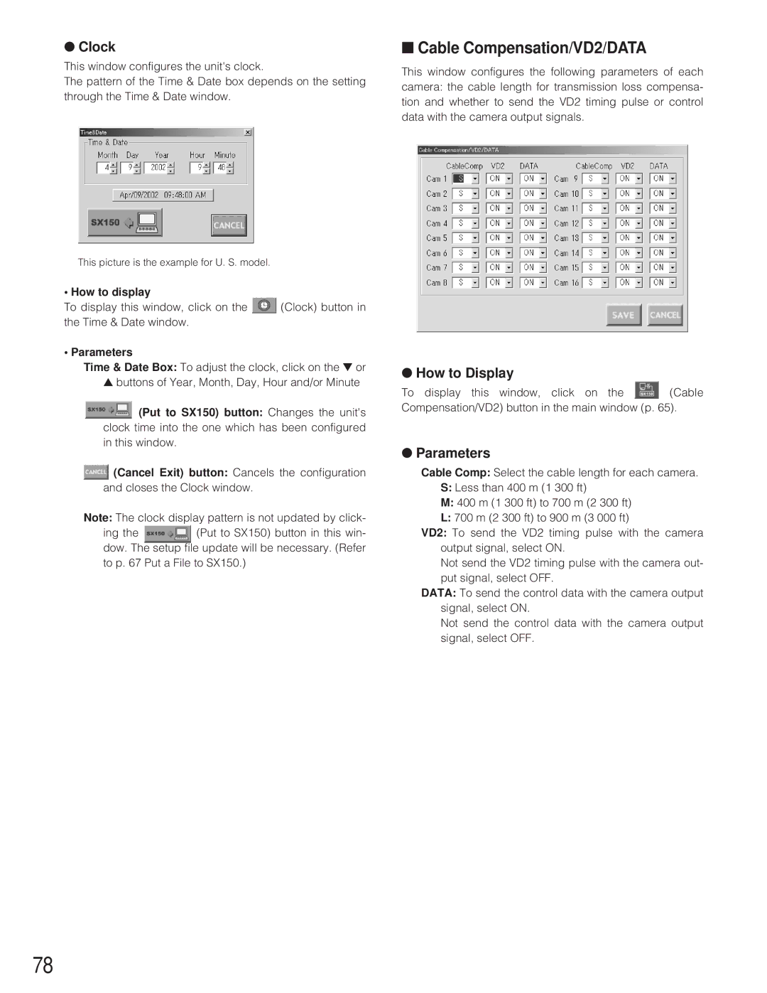
■Cable Compensation/VD2/DATA
This window configures the following parameters of each camera: the cable length for transmission loss compensa- tion and whether to send the VD2 timing pulse or control data with the camera output signals.
●How to Display
To display this window, click on the ![]() (Cable Compensation/VD2) button in the main window (p. 65).
(Cable Compensation/VD2) button in the main window (p. 65).
●Parameters
Cable Comp: Select the cable length for each camera.
S:Less than 400 m (1 300 ft)
M:400 m (1 300 ft) to 700 m (2 300 ft)
L:700 m (2 300 ft) to 900 m (3 000 ft)
VD2: To send the VD2 timing pulse with the camera output signal, select ON.
Not send the VD2 timing pulse with the camera out- put signal, select OFF.
DATA: To send the control data with the camera output signal, select ON.
Not send the control data with the camera output signal, select OFF.
78
