1
1
1
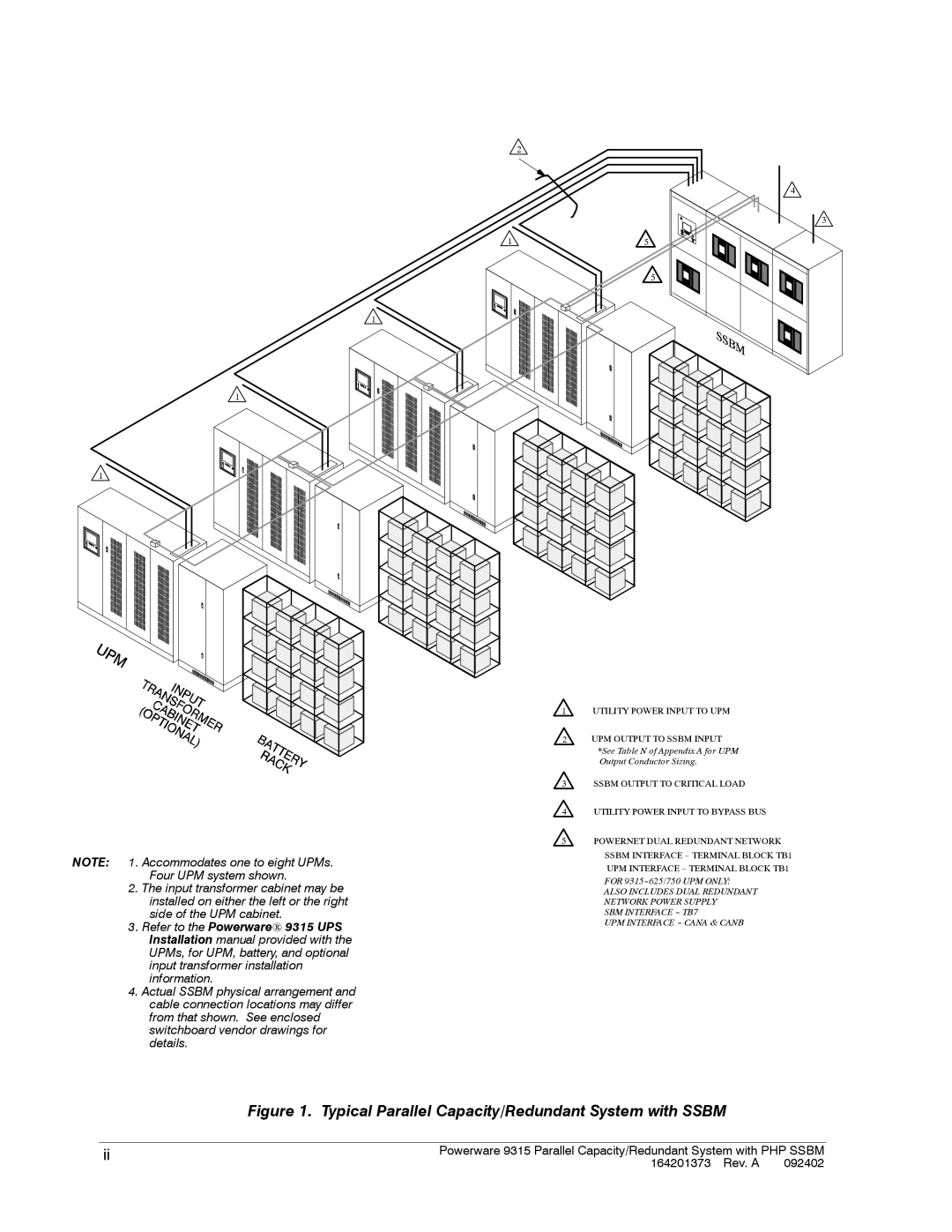
NOTE: 1. Accommodates one to eight UPMs. Four UPM system shown.
2.The input transformer cabinet may be installed on either the left or the right side of the UPM cabinet.
3.Refer to the Powerware 9315 UPS Installation manual provided with the UPMs, for UPM, battery, and optional input transformer installation information.
4.Actual SSBM physical arrangement and cable connection locations may differ from that shown. See enclosed switchboard vendor drawings for details.
2
1
4
3
5
5
1UTILITY POWER INPUT TO UPM
2UPM OUTPUT TO SSBM INPUT *See Table N of Appendix A for UPM Output Conductor Sizing.
3SSBM OUTPUT TO CRITICAL LOAD
4UTILITY POWER INPUT TO BYPASS BUS
5POWERNET DUAL REDUNDANT NETWORK SSBM INTERFACE
FOR
ALSO INCLUDES DUAL REDUNDANT NETWORK POWER SUPPLY
SBM INTERFACE
UPM INTERFACE
Figure 1. Typical Parallel Capacity/Redundant System with SSBM
ii | Powerware 9315 Parallel Capacity/Redundant System with PHP SSBM | |
| 164201373 Rev. A | 092402 |