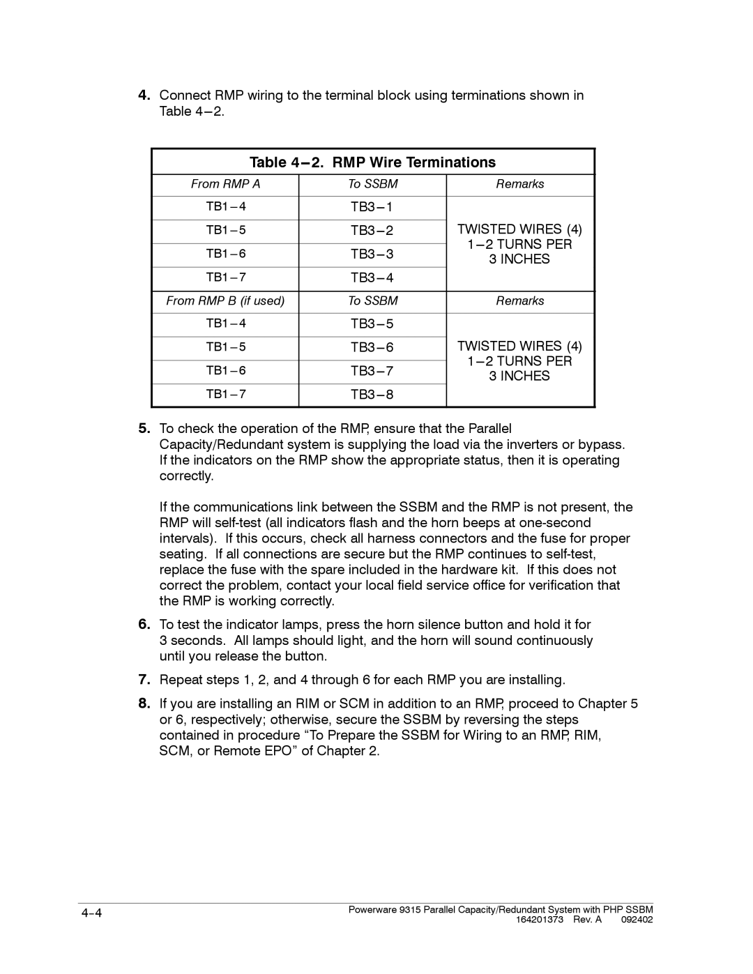
4.Connect RMP wiring to the terminal block using terminations shown in Table
Table 4---2. RMP Wire Terminations
From RMP A | To SSBM | Remarks | |
|
|
| |
| |||
|
| TWISTED WIRES (4) | |
|
| ||
3 INCHES | |||
|
| ||
| |||
|
|
| |
From RMP B (if used) | To SSBM | Remarks | |
|
|
| |
| |||
|
| TWISTED WIRES (4) | |
|
| ||
3 INCHES | |||
|
| ||
| |||
|
|
|
5.To check the operation of the RMP, ensure that the Parallel Capacity/Redundant system is supplying the load via the inverters or bypass. If the indicators on the RMP show the appropriate status, then it is operating correctly.
If the communications link between the SSBM and the RMP is not present, the RMP will
6.To test the indicator lamps, press the horn silence button and hold it for
3 seconds. All lamps should light, and the horn will sound continuously until you release the button.
7.Repeat steps 1, 2, and 4 through 6 for each RMP you are installing.
8.If you are installing an RIM or SCM in addition to an RMP, proceed to Chapter 5 or 6, respectively; otherwise, secure the SSBM by reversing the steps contained in procedure “To Prepare the SSBM for Wiring to an RMP, RIM, SCM, or Remote EPO” of Chapter 2.
Powerware 9315 Parallel Capacity/Redundant System with PHP SSBM | |
| 164201373 Rev. A 092402 |