Using the Control Panel
9.1Description
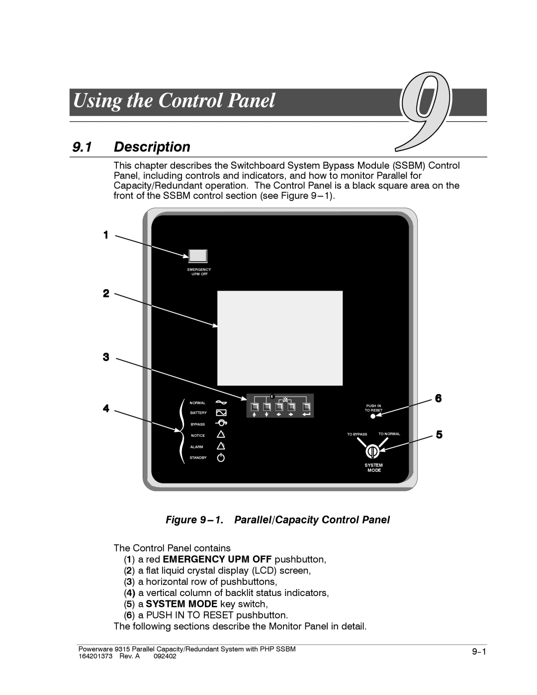
This chapter describes the Switchboard System Bypass Module (SSBM) Control Panel, including controls and indicators, and how to monitor Parallel for Capacity/Redundant operation. The Control Panel is a black square area on the front of the SSBM control section (see Figure
EMERGENCY
UPM OFF
NORMAL
BATTERY
BYPASS
NOTICE
ALARM
STANDBY
PUSH IN
TO RESET
TO BYPASS | TO NORMAL |
SYSTEM
MODE
Figure 9---1. Parallel/Capacity Control Panel
The Control Panel contains
(1) a red EMERGENCY UPM OFF pushbutton,
(2) a flat liquid crystal display (LCD) screen,
(3) a horizontal row of pushbuttons,
(4) a vertical column of backlit status indicators, (5) a SYSTEM MODE key switch,
(6) a PUSH IN TO RESET pushbutton.
The following sections describe the Monitor Panel in detail.
Powerware 9315 Parallel Capacity/Redundant System with PHP SSBM | |
164201373 Rev. A 092402 |
|