1.Two redundant PowerNet control networks connect the UPMs to each other and the UPMs to the SSBM. Each network requires only one shielded twisted pair of wires.
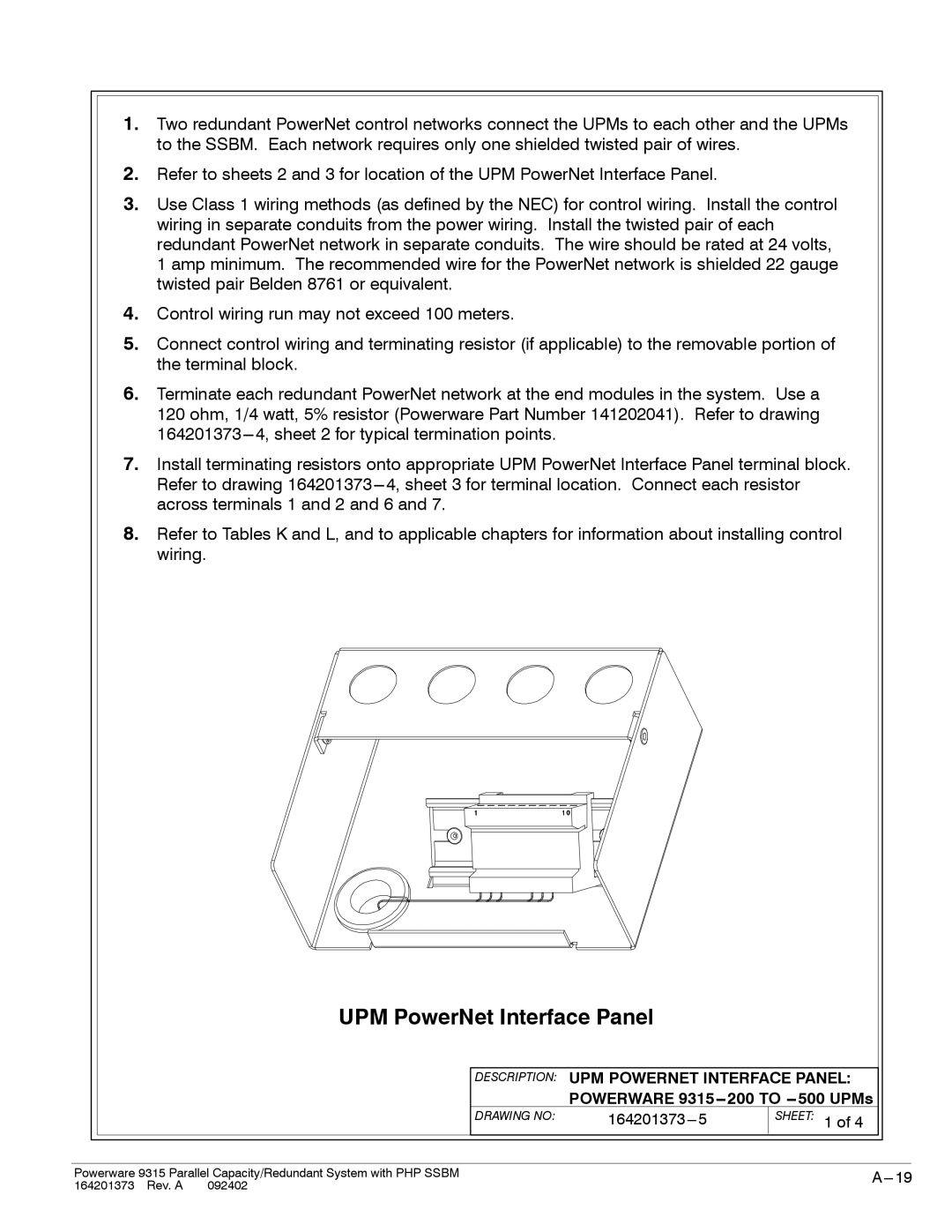
2.Refer to sheets 2 and 3 for location of the UPM PowerNet Interface Panel.
3.Use Class 1 wiring methods (as defined by the NEC) for control wiring. Install the control wiring in separate conduits from the power wiring. Install the twisted pair of each redundant PowerNet network in separate conduits. The wire should be rated at 24 volts,
1 amp minimum. The recommended wire for the PowerNet network is shielded 22 gauge twisted pair Belden 8761 or equivalent.
4.Control wiring run may not exceed 100 meters.
5.Connect control wiring and terminating resistor (if applicable) to the removable portion of the terminal block.
6.Terminate each redundant PowerNet network at the end modules in the system. Use a
120 ohm, 1/4 watt, 5% resistor (Powerware Part Number 141202041). Refer to drawing
7.Install terminating resistors onto appropriate UPM PowerNet Interface Panel terminal block. Refer to drawing
8.Refer to Tables K and L, and to applicable chapters for information about installing control wiring.
UPM PowerNet Interface Panel
DESCRIPTION: UPM POWERNET INTERFACE PANEL:
POWERWARE 9315-- 200 TO -- 500 UPMs
DRAWING NO: |
|
SHEET: 1 of 4
Powerware 9315 Parallel Capacity/Redundant System with PHP SSBM | |
164201373 Rev. A 092402 |
|