NOTE: 1. Accommodates one to eight UPMs. Four UPM system shown.
NOTE: 2. A bypass neutral feeder must be installed when the output neutral is used. If no bypass neutral is installed, the output neutral is to be bonded to the chassis in the SSBM through the minimum size copper conductor listed in Table H. In either case, fully rated neutral conductors are to be run from the output of each UPM to the neutral bus bar inside the SSBM.
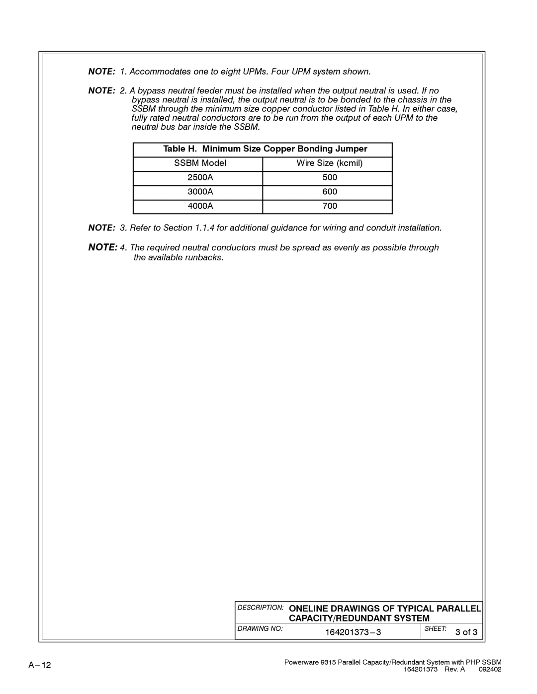
Table H. Minimum Size Copper Bonding Jumper
SSBM Model | Wire Size (kcmil) |
2500A | 500 |
3000A | 600 |
4000A | 700 |
NOTE: 3. Refer to Section 1.1.4 for additional guidance for wiring and conduit installation.
NOTE: 4. The required neutral conductors must be spread as evenly as possible through the available runbacks.
DESCRIPTION: ONELINE DRAWINGS OF TYPICAL PARALLEL
CAPACITY/REDUNDANT SYSTEM
DRAWING NO: |
|
|
SHEET: 3 of 3
|
|
|
Powerware 9315 Parallel Capacity/Redundant System with PHP SSBM | ||
| 164201373 Rev. A 092402 | |