To install a Remote EPO control:
1.Securely mount the Remote EPO station. Recommended locations include operator’s consoles or exit doors.
2.Install wiring from the Remote EPO station using
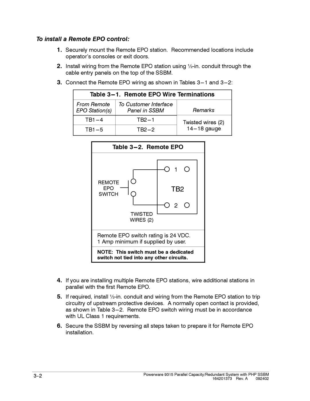
3.Connect the Remote EPO wiring as shown in Tables
Table 3---1. Remote EPO Wire Terminations
From Remote | To Customer Interface | ||
EPO Station(s) | Panel in SSBM | ||
|
|
|
|
4 | 1 | ||
|
|
|
|
5 | 2 | ||
|
|
|
|
Remarks
Twisted wires (2)
Table 3---2. Remote EPO
1
REMOTE
EPOTB2
SWITCH
2
TWISTED
WIRES (2)
Remote EPO switch rating is 24 VDC. 1 Amp minimum if supplied by user.
NOTE: This switch must be a dedicated switch not tied into any other circuits.
4.If you are installing multiple Remote EPO stations, wire additional stations in parallel with the first Remote EPO.
5.If required, install
6.Secure the SSBM by reversing all steps taken to prepare it for Remote EPO installation.
Powerware 9315 Parallel Capacity/Redundant System with PHP SSBM | |
| 164201373 Rev. A 092402 |