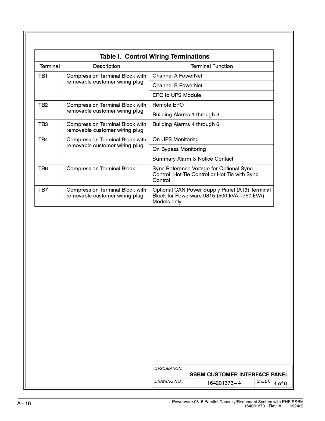
Table I. Control Wiring Terminations
Terminal | Description | Terminal Function |
|
|
|
TB1 | Compression Terminal Block with | Channel A PowerNet |
| removable customer wiring plug |
|
| Channel B PowerNet | |
|
| |
|
|
|
|
| EPO to UPS Module |
|
|
|
TB2 | Compression Terminal Block with | Remote EPO |
| removable customer wiring plug |
|
| Building Alarms 1 through 3 | |
|
| |
|
|
|
TB3 | Compression Terminal Block with | Building Alarms 4 through 6 |
| removable customer wiring plug |
|
|
|
|
TB4 | Compression Terminal Block with | On UPS Monitoring |
| removable customer wiring plug |
|
| On Bypass Monitoring | |
|
| |
|
|
|
|
| Summary Alarm & Notice Contact |
|
|
|
TB6 | Compression Terminal Block | Sync Reference Voltage for Optional Sync |
|
| Control, |
|
| Control |
|
|
|
TB7 | Compression Terminal Block with | Optional CAN Power Supply Panel (A13) Terminal |
| removable customer wiring plug | Block for Powerware 9315 (500 |
|
| Models only |
|
|
|
DESCRIPTION:
SSBM CUSTOMER INTERFACE PANEL
DRAWING NO: |
|
SHEET: 4 of 6
|
|
|
Powerware 9315 Parallel Capacity/Redundant System with PHP SSBM | ||
| 164201373 Rev. A 092402 | |