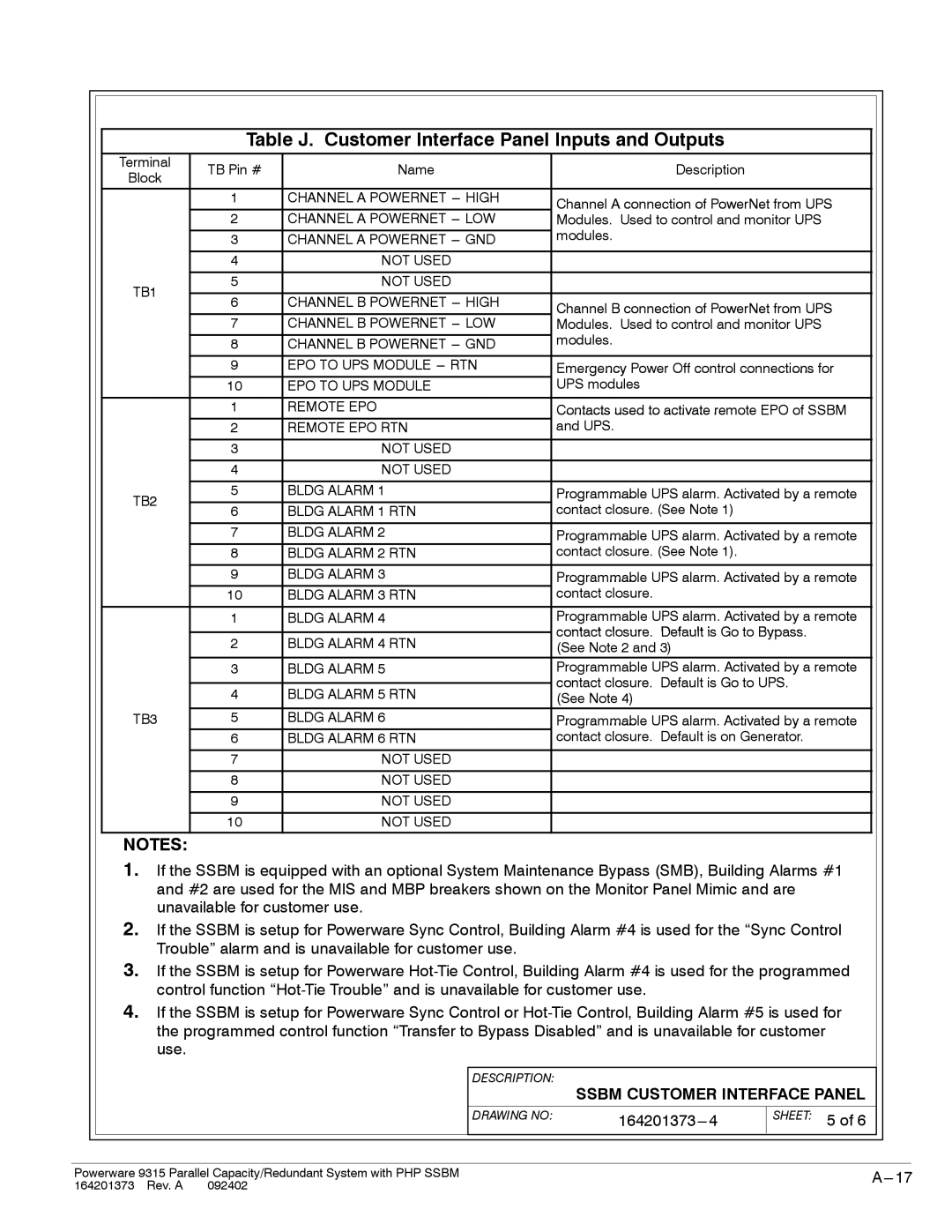
Table J. Customer Interface Panel Inputs and Outputs
Terminal | TB Pin # | Name | Description | |
Block | ||||
|
|
| ||
| 1 | CHANNEL A POWERNET | Channel A connection of PowerNet from UPS | |
|
|
| ||
| 2 | CHANNEL A POWERNET | Modules. Used to control and monitor UPS | |
|
|
| modules. | |
| 3 | CHANNEL A POWERNET | ||
|
|
|
| |
| 4 | NOT USED |
| |
|
|
|
| |
TB1 | 5 | NOT USED |
| |
|
|
| ||
6 | CHANNEL B POWERNET | Channel B connection of PowerNet from UPS | ||
| ||||
| 7 | CHANNEL B POWERNET | Modules. Used to control and monitor UPS | |
|
|
| modules. | |
| 8 | CHANNEL B POWERNET | ||
| 9 | EPO TO UPS MODULE | Emergency Power Off control connections for | |
| 10 | EPO TO UPS MODULE | UPS modules | |
| 1 | REMOTE EPO | Contacts used to activate remote EPO of SSBM | |
| 2 | REMOTE EPO RTN | and UPS. | |
|
|
|
| |
| 3 | NOT USED |
| |
|
|
|
| |
| 4 | NOT USED |
| |
|
|
|
| |
TB2 | 5 | BLDG ALARM 1 | Programmable UPS alarm. Activated by a remote | |
6 | BLDG ALARM 1 RTN | contact closure. (See Note 1) | ||
| ||||
|
|
|
| |
| 7 | BLDG ALARM 2 | Programmable UPS alarm. Activated by a remote | |
| 8 | BLDG ALARM 2 RTN | contact closure. (See Note 1). | |
|
|
|
| |
| 9 | BLDG ALARM 3 | Programmable UPS alarm. Activated by a remote | |
| 10 | BLDG ALARM 3 RTN | contact closure. | |
| 1 | BLDG ALARM 4 | Programmable UPS alarm. Activated by a remote | |
|
|
| contact closure. Default is Go to Bypass. | |
| 2 | BLDG ALARM 4 RTN | ||
| (See Note 2 and 3) | |||
| 3 | BLDG ALARM 5 | Programmable UPS alarm. Activated by a remote | |
|
|
| contact closure. Default is Go to UPS. | |
| 4 | BLDG ALARM 5 RTN | ||
| (See Note 4) | |||
TB3 | 5 | BLDG ALARM 6 | Programmable UPS alarm. Activated by a remote | |
| 6 | BLDG ALARM 6 RTN | contact closure. Default is on Generator. | |
| 7 | NOT USED |
| |
| 8 | NOT USED |
| |
|
|
|
| |
| 9 | NOT USED |
| |
|
|
|
| |
| 10 | NOT USED |
|
NOTES:
1.If the SSBM is equipped with an optional System Maintenance Bypass (SMB), Building Alarms #1 and #2 are used for the MIS and MBP breakers shown on the Monitor Panel Mimic and are unavailable for customer use.
2.If the SSBM is setup for Powerware Sync Control, Building Alarm #4 is used for the “Sync Control Trouble” alarm and is unavailable for customer use.
3.If the SSBM is setup for Powerware
4.If the SSBM is setup for Powerware Sync Control or
DESCRIPTION:
SSBM CUSTOMER INTERFACE PANEL
DRAWING NO: |
|
SHEET: 5 of 6
Powerware 9315 Parallel Capacity/Redundant System with PHP SSBM | |
164201373 Rev. A 092402 |
|