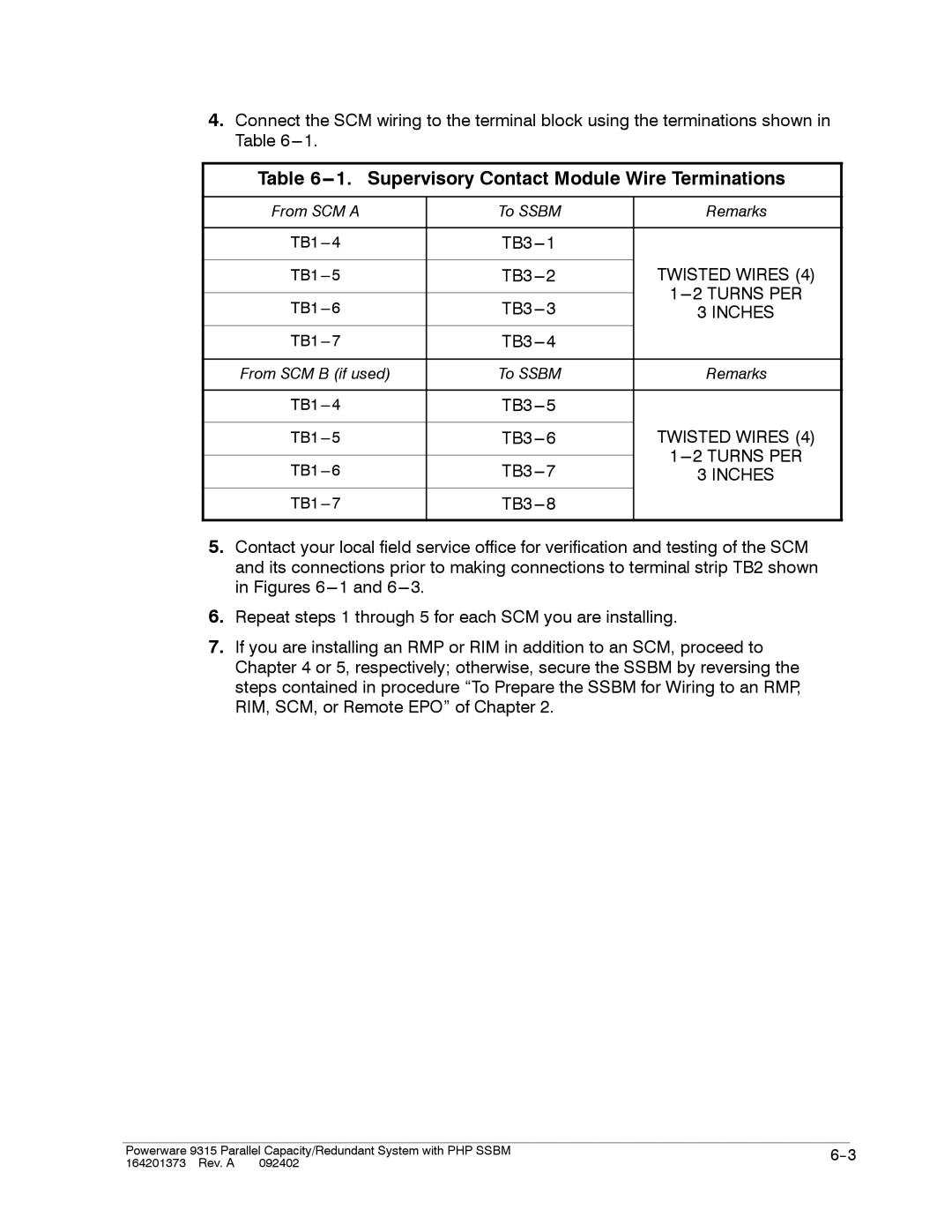
4.Connect the SCM wiring to the terminal block using the terminations shown in Table
Table 6---1. Supervisory Contact Module Wire Terminations
From SCM A | To SSBM | Remarks | |
|
|
| |
| |||
|
| TWISTED WIRES (4) | |
|
| ||
3 INCHES | |||
|
|
| |
| |||
|
|
| |
From SCM B (if used) | To SSBM | Remarks | |
|
|
| |
| |||
|
| TWISTED WIRES (4) | |
|
| ||
3 INCHES | |||
|
|
| |
| |||
|
|
|
5.Contact your local field service office for verification and testing of the SCM and its connections prior to making connections to terminal strip TB2 shown in Figures
6.Repeat steps 1 through 5 for each SCM you are installing.
7.If you are installing an RMP or RIM in addition to an SCM, proceed to Chapter 4 or 5, respectively; otherwise, secure the SSBM by reversing the steps contained in procedure “To Prepare the SSBM for Wiring to an RMP, RIM, SCM, or Remote EPO” of Chapter 2.
|
|
|
Powerware 9315 Parallel Capacity/Redundant System with PHP SSBM | ||
164201373 Rev. A 092402 |
|
|