B ![]()
ALARM PINOUT
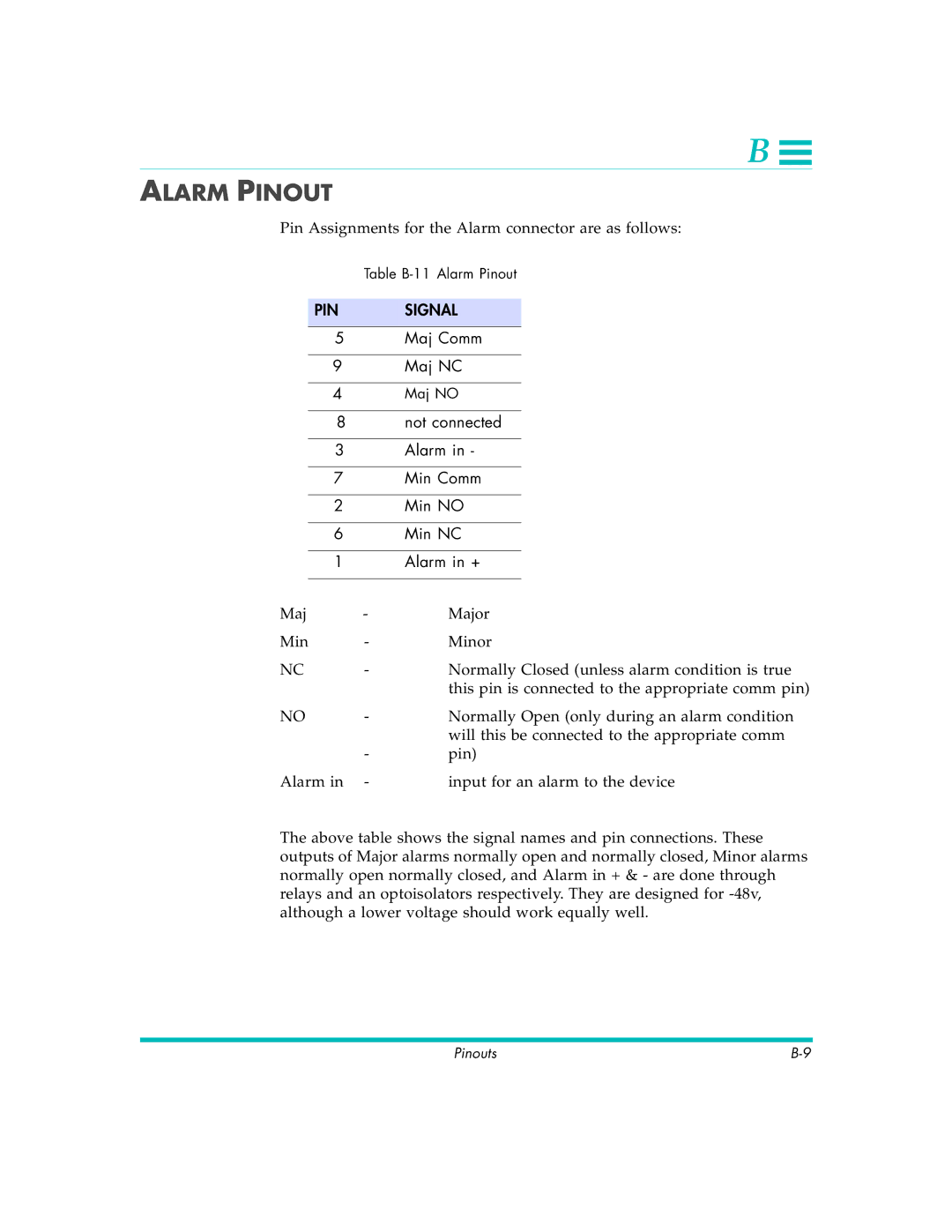
Pin Assignments for the Alarm connector are as follows:
|
| Table | ||
|
|
|
| |
| PIN |
| SIGNAL |
|
|
|
|
|
|
5 |
| Maj Comm | ||
|
|
|
|
|
9 |
| Maj NC | ||
|
|
|
|
|
4 |
| Maj NO | ||
|
|
|
|
|
8 |
| not connected | ||
|
|
|
|
|
3 |
| Alarm in - | ||
|
|
|
|
|
7 |
| Min Comm | ||
|
|
|
|
|
2 |
| Min NO | ||
|
|
|
|
|
6 |
| Min NC | ||
|
|
|
|
|
1 |
| Alarm in + | ||
|
|
|
|
|
Maj | - | Major | ||
Min | - | Minor | ||
NC | - | Normally Closed (unless alarm condition is true | ||
|
|
| this pin is connected to the appropriate comm pin) | |
NO | - | Normally Open (only during an alarm condition | ||
|
|
| will this be connected to the appropriate comm | |
|
| - | pin) | |
Alarm in | - | input for an alarm to the device | ||
The above table shows the signal names and pin connections. These outputs of Major alarms normally open and normally closed, Minor alarms normally open normally closed, and Alarm in + & - are done through relays and an optoisolators respectively. They are designed for
Pinouts |
