5 ![]()
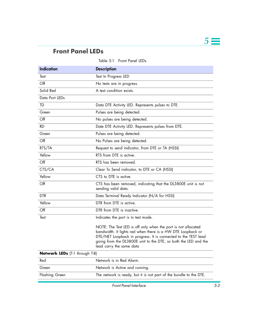
Front Panel LEDs
| Table |
|
|
Indication | Description |
|
|
Test | Test In Progress LED |
|
|
Off | No tests are in progress. |
|
|
Solid Red | A test condition exists. |
|
|
Data Port LEDs |
|
|
|
TD | Data DTE Activity LED. Represents pulses to DTE. |
|
|
Green | Pulses are being detected. |
|
|
Off | No pulses are being detected. |
|
|
RD | Date DTE Activity LED. Represents pulses from DTE. |
|
|
Green | Pulses are being detected. |
|
|
Off | No Pulses are being detected. |
|
|
RTS/TA | Request to send indicator, from DTE or TA (HSSI) |
|
|
Yellow | RTS from DTE is active. |
|
|
Off | RTS has been removed. |
|
|
CTS/CA | Clear To Send indicator, to DTE or CA (HSSI) |
|
|
Yellow | CTS to DTE is active. |
|
|
Off | CTS has been removed, indicating that the DL3800E unit is not |
| sending valid data. |
|
|
DTR | Data Terminal Ready Indicator (N/A for HSSI) |
|
|
Yellow | DTR from DTE is active. |
|
|
Off | DTR from DTE is inactive. |
|
|
Test | Indicates the port is in test mode. |
| NOTE: The Test LED is off only when the port is not allocated |
| bandwidth. It lights red when there is a HW DTE Loopback or |
| DTE/NET Loopback in progress. It is connected to the TEST lead |
| going from the DL3800E unit to the DTE, so both the LED and the |
| lead carry the same data |
Network LEDs
Red | Network is in Red Alarm. |
|
|
|
|
Green | Network is Active and running. |
|
|
|
|
Flashing Green | The network is ready, but it is not part of the bundle to the DTE. |
|
|
|
|
|
|
|
Front Panel Interface |