3.In the Properties section, select the port property values that match those used by the connected serial console device.
The Module supports these port property settings:
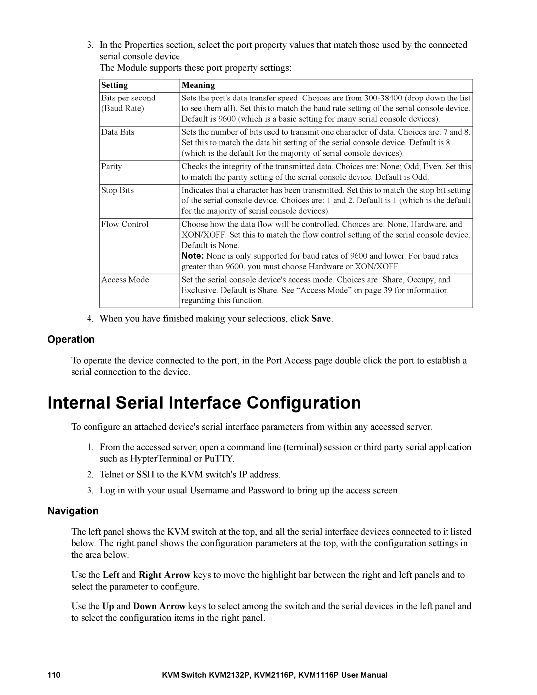
Setting | Meaning |
Bits per second | Sets the port's data transfer speed. Choices are from |
(Baud Rate) | to see them all). Set this to match the baud rate setting of the serial console device. |
| Default is 9600 (which is a basic setting for many serial console devices). |
|
|
Data Bits | Sets the number of bits used to transmit one character of data. Choices are: 7 and 8. |
| Set this to match the data bit setting of the serial console device. Default is 8 |
| (which is the default for the majority of serial console devices). |
|
|
Parity | Checks the integrity of the transmitted data. Choices are: None; Odd; Even. Set this |
| to match the parity setting of the serial console device. Default is Odd. |
|
|
Stop Bits | Indicates that a character has been transmitted. Set this to match the stop bit setting |
| of the serial console device. Choices are: 1 and 2. Default is 1 (which is the default |
| for the majority of serial console devices). |
|
|
Flow Control | Choose how the data flow will be controlled. Choices are: None, Hardware, and |
| XON/XOFF. Set this to match the flow control setting of the serial console device. |
| Default is None. |
| Note: None is only supported for baud rates of 9600 and lower. For baud rates |
| greater than 9600, you must choose Hardware or XON/XOFF. |
|
|
Access Mode | Set the serial console device's access mode. Choices are: Share, Occupy, and |
| Exclusive. Default is Share. See “Access Mode” on page 39 for information |
| regarding this function. |
|
|
4. When you have finished making your selections, click Save.
Operation
To operate the device connected to the port, in the Port Access page double click the port to establish a serial connection to the device.
Internal Serial Interface Configuration
To configure an attached device's serial interface parameters from within any accessed server.
1.From the accessed server, open a command line (terminal) session or third party serial application such as HypterTerminal or PuTTY.
2.Telnet or SSH to the KVM switch's IP address.
3.Log in with your usual Username and Password to bring up the access screen.
Navigation
The left panel shows the KVM switch at the top, and all the serial interface devices connected to it listed below. The right panel shows the configuration parameters at the top, with the configuration settings in the area below.
Use the Left and Right Arrow keys to move the highlight bar between the right and left panels and to select the parameter to configure.
Use the Up and Down Arrow keys to select among the switch and the serial devices in the left panel and to select the configuration items in the right panel.
110 | KVM Switch KVM2132P, KVM2116P, KVM1116P User Manual |