Page | Robertson AP45 Autopilot |
| Trouble shooting |
G45 GYRO INTERFACE
Readjusting procedure of 2,5V reference voltage (VR4) in case of extension of autopilot interconnection cable:
1.Disconnect
2.Enter Debug mode in AP45. (See page
3.Step through the loop until you find “Flux Sin” and/or “Flux Cos”.
4.Adjust RV4 until sin/cos reads exactly 2.50 V.
5.Reconnect the
6.Verify correct heading readout on AP45 in Manual mode compared to the Gyrocompass.
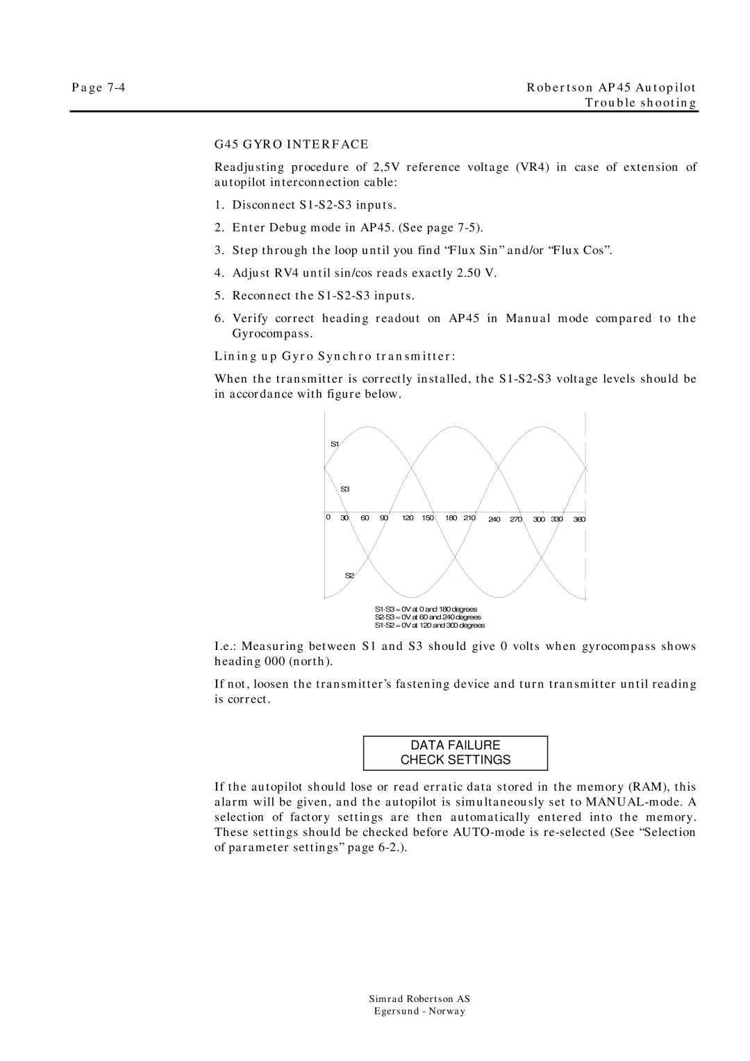
Lining up Gyro Synchro transmitter:
When the transmitter is correctly installed, the
S1
S3
0 | 30 | 60 | 90 | 120 | 150 | 180 | 210 | 240 | 270 | 300 | 330 | 360 |
S2
I.e.: Measuring between S1 and S3 should give 0 volts when gyrocompass shows heading 000 (north).
If not, loosen the transmitter’s fastening device and turn transmitter until reading is correct.
DATA FAILURE
CHECK SETTINGS
If the autopilot should lose or read erratic data stored in the memory (RAM), this alarm will be given, and the autopilot is simultaneously set to
Simrad Robertson AS
Egersund - Norway