Robertson AP45 Autopilot | Page | |
Installation |
|
|
G45 Gyro Interface | The G45 is required when a gyrocompass with 1:1 ratio | synchro signal is |
Unit | connected to AP45. |
|
There is separate terminals for high voltage (80V
G45 can also be used for excitation of a “dead” synchro transmitter.
The unit shall be mounted within the cable length (3 m) from the autopilot control unit. In case the cable has to be extended, the 2.5V reference voltage must be checked and eventually readjusted in accordance with “TROUBLE SHOOTING”, page
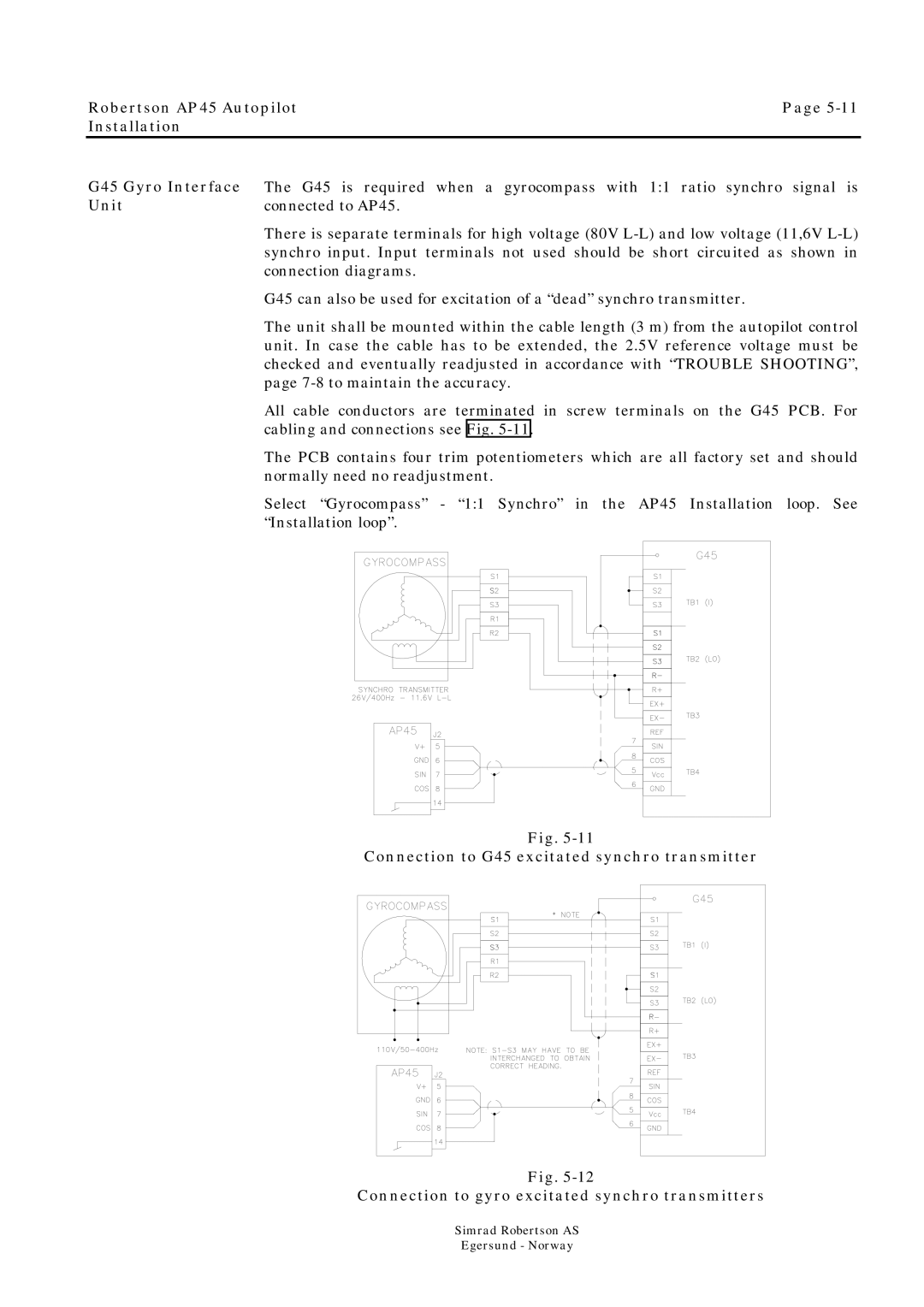
All cable conductors are terminated in screw terminals on the G45 PCB. For cabling and connections see Fig.
The PCB contains four trim potentiometers which are all factory set and should normally need no readjustment.
Select “Gyrocompass” - “1:1 Synchro” in the AP45 Installation loop. See “Installation loop”.
Fig.
Connection to G45 excitated synchro transmitter
Fig.
Connection to gyro excitated synchro transmitters