Robertson AP45 Autopilot | Page |
Installation |
|
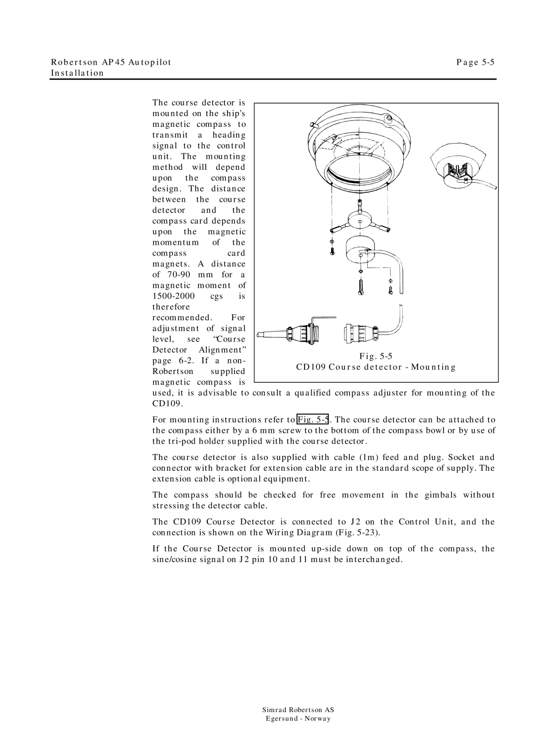
The course detector is mounted on the ship's
magnetic compass to transmit a heading
signal to the control unit. The mounting
method will depend upon the compass design. The distance between the course
detector and the compass card depends upon the magnetic momentum of the
compass card magnets. A distance
of
recommended. For
adjustment of signal level, see “Course Detector Alignment”
page
used, it is advisable to consult a qualified compass adjuster for mounting of the CD109.
For mounting instructions refer to Fig.
The course detector is also supplied with cable (1m) feed and plug. Socket and connector with bracket for extension cable are in the standard scope of supply. The extension cable is optional equipment.
The compass should be checked for free movement in the gimbals without stressing the detector cable.
The CD109 Course Detector is connected to J2 on the Control Unit, and the connection is shown on the Wiring Diagram (Fig.
If the Course Detector is mounted
Simrad Robertson AS
Egersund - Norway