Page 5-10 | Robertson AP45 Autopilot |
| Installation |
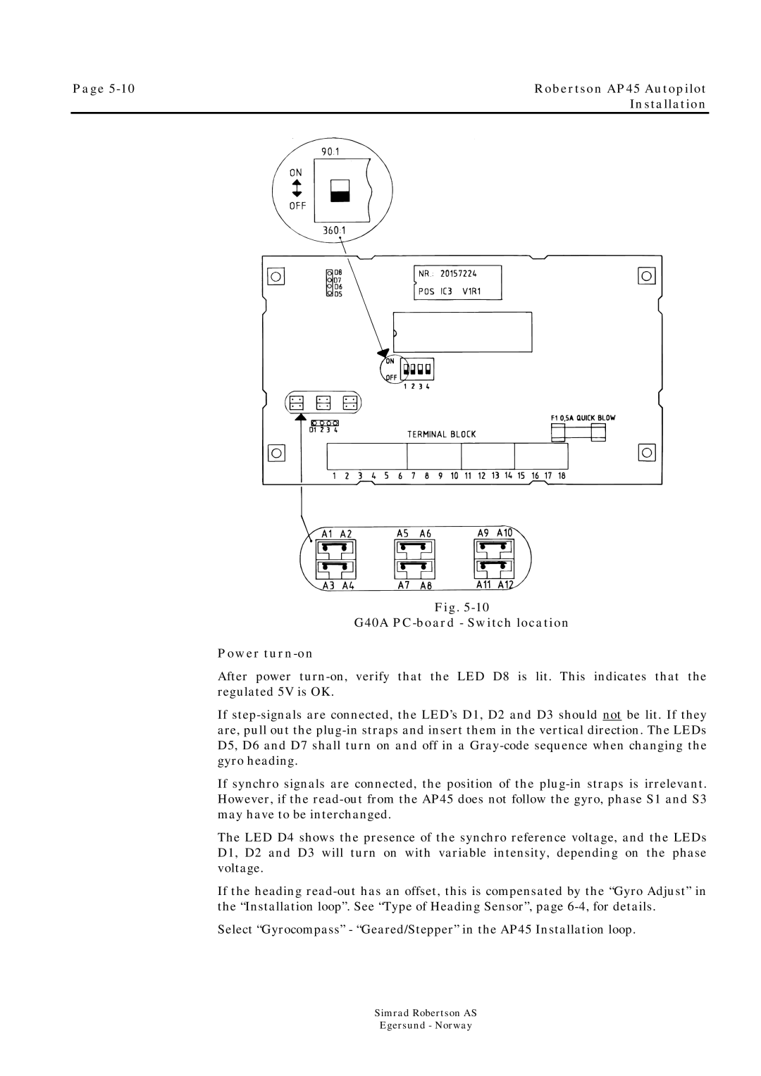
Fig. 5-10
G40A PC-board - Switch location
Power turn-on
After power turn-on, verify that the LED D8 is lit. This indicates that the regulated 5V is OK.
If step-signals are connected, the LED’s D1, D2 and D3 should not be lit. If they are, pull out the plug-in straps and insert them in the vertical direction. The LEDs D5, D6 and D7 shall turn on and off in a Gray-code sequence when changing the gyro heading.
If synchro signals are connected, the position of the plug-in straps is irrelevant. However, if the read-out from the AP45 does not follow the gyro, phase S1 and S3 may have to be interchanged.
The LED D4 shows the presence of the synchro reference voltage, and the LEDs D1, D2 and D3 will turn on with variable intensity, depending on the phase voltage.
If the heading read-out has an offset, this is compensated by the “Gyro Adjust” in the “Installation loop”. See “Type of Heading Sensor”, page 6-4,for details.
Select “Gyrocompass” - “Geared/Stepper” in the AP45 Installation loop.
Simrad Robertson AS
Egersund - Norway