Page | Robertson AP45 Autopilot |
| Installation |
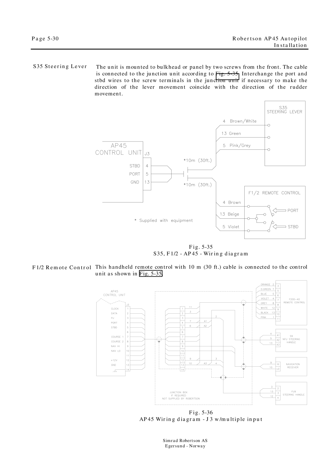
S35 Steering Lever
F1/2 Remote Control
The unit is mounted to bulkhead or panel by two screws from the front. The cable is connected to the junction unit according to Fig.
Fig.
S35, F1/2 - AP45 - Wiring diagram
This handheld remote control with 10 m (30 ft.) cable is connected to the control unit as shown in Fig.
Fig.
AP45 Wiring diagram - J3 w/multiple input
Simrad Robertson AS
Egersund - Norway