Page | Robertson AP45 Autopilot |
|
Rudder speed
Course Detector Alignment
Selection of parameter settings
The rudder speed is a contributing factor to autopilot performance.
For the majority of vessels a rudder speed of
The rudder speed can easily be calculated by the following equation:
If a Robertson power unit has been installed, the speed can be adjusted in two ways dependant on the type of unit.
1.Reversible units using the J45A Junction Unit: By adjustment of the RV1 potentiometer.
2.Continuously running pump units
If a
Note!
If the rudder speed can not be set within the recommended limits, perform the sea trial before any further steps are taken. Some vessels may steer satisfactory even with a rudder speed exceeding the recommended limits.
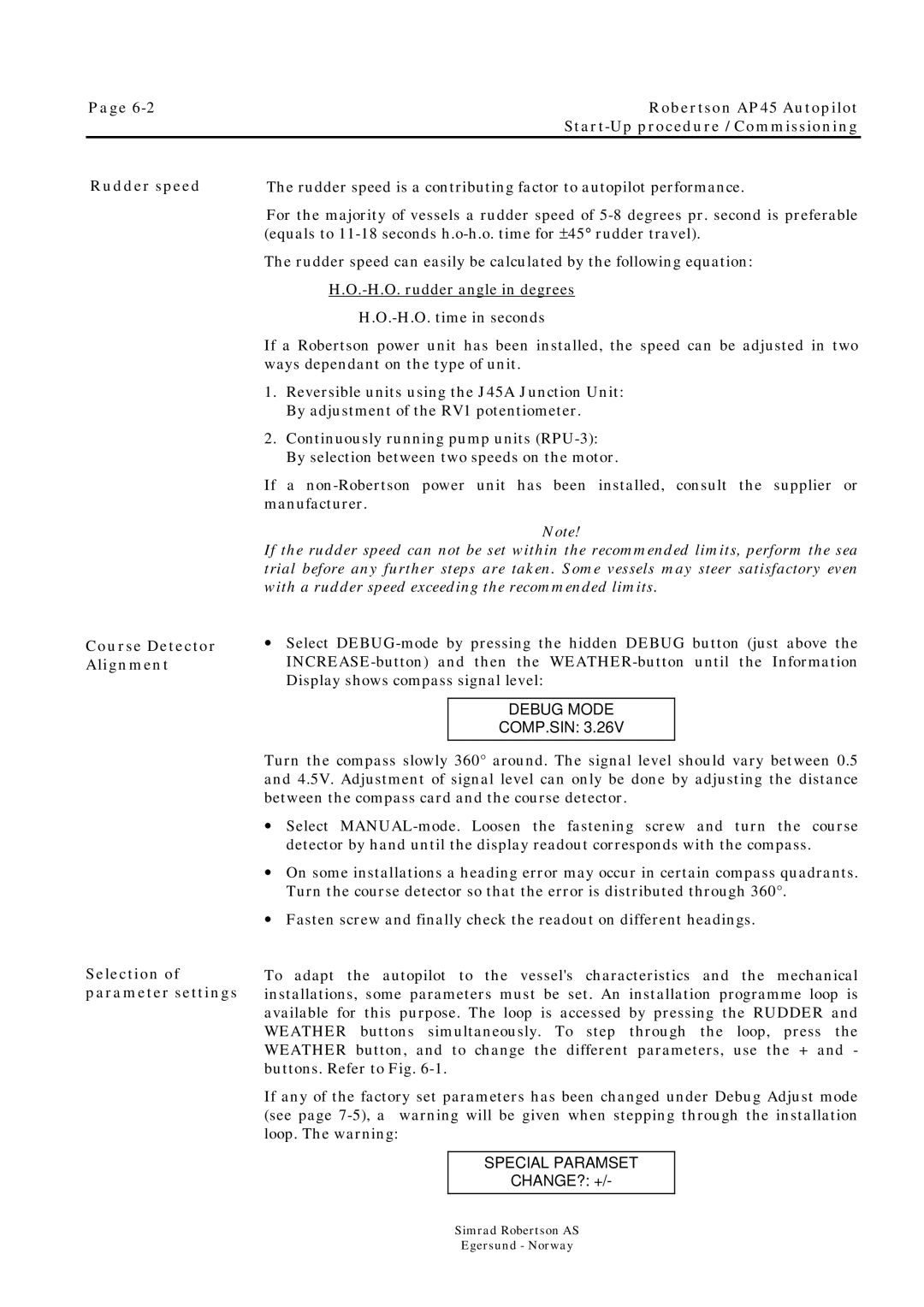
•Select
DEBUG MODE
COMP.SIN: 3.26V
Turn the compass slowly 360° around. The signal level should vary between 0.5 and 4.5V. Adjustment of signal level can only be done by adjusting the distance between the compass card and the course detector.
•Select
•On some installations a heading error may occur in certain compass quadrants. Turn the course detector so that the error is distributed through 360°.
•Fasten screw and finally check the readout on different headings.
To adapt the autopilot to the vessel's characteristics and the mechanical installations, some parameters must be set. An installation programme loop is available for this purpose. The loop is accessed by pressing the RUDDER and WEATHER buttons simultaneously. To step through the loop, press the WEATHER button, and to change the different parameters, use the + and - buttons. Refer to Fig.
If any of the factory set parameters has been changed under Debug Adjust mode (see page
SPECIAL PARAMSET
CHANGE?: +/-
Simrad Robertson AS
Egersund - Norway