Robertson AP45 Autopilot | Page |
Installation |
|
J45A Junction Unit The junction unit is made for bulkhead mounting and secured by two screws. To minimise length of power cables (thus avoiding voltage drop), it should be centrally located between mains panel and power unit.
The unit has separate mains supply for autopilot electronics and power unit motor. This reduces the interference to the autopilot electronics caused by the motor switching. The power unit supply cable (mains supply) should be of at least 4 mm2 (AWG10) size. The electronic supply cable should be 1,5 mm2 (AWG14).
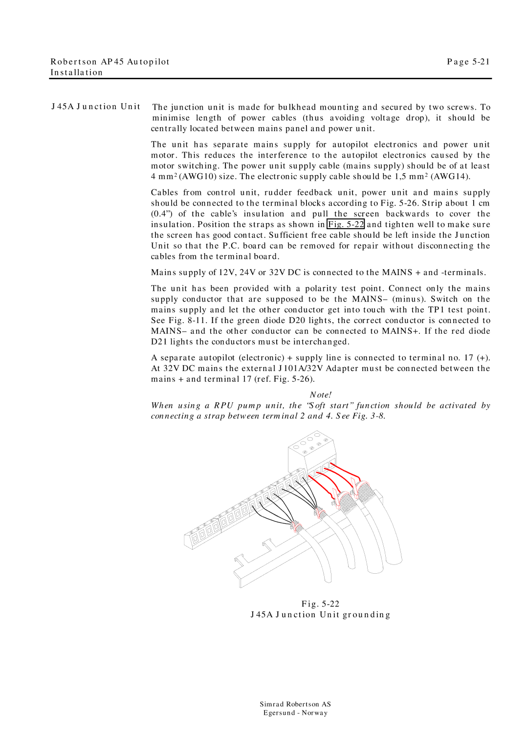
Cables from control unit, rudder feedback unit, power unit and mains supply should be connected to the terminal blocks according to Fig.
Mains supply of 12V, 24V or 32V DC is connected to the MAINS + and
The unit has been provided with a polarity test point. Connect only the mains supply conductor that are supposed to be the MAINS– (minus). Switch on the mains supply and let the other conductor get into touch with the TP1 test point. See Fig.
A separate autopilot (electronic) + supply line is connected to terminal no. 17 (+). At 32V DC mains the external J101A/32V Adapter must be connected between the mains + and terminal 17 (ref. Fig.
Note!
When using a RPU pump unit, the “Soft start” function should be activated by connecting a strap between terminal 2 and 4. See Fig.
Fig.
J45A Junction Unit grounding
Simrad Robertson AS
Egersund - Norway