Page | Robertson AP45 Autopilot | |
| Design and theory of operation | |
|
|
|
Junction Units J45S Junction Unit
RF14XU is equipped with two sets of limit switches. One set can be connected in series with the autopilot solid state switch, the other can be incorporated in an independent hand steering system, if required.
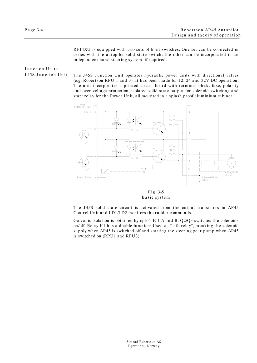
The J45S Junction Unit operates hydraulic power units with directional valves (e.g. Robertson RPU 1 and 3). It has been made for 12, 24 and 32V DC operation. The unit incorporates a printed circuit board with terminal block, fuse, polarity and over voltage protection, isolated solid state output for solenoid switching and start relay for the Power Unit, all mounted in a splash proof aluminium cabinet.
Fig.
Basic system
The J45S solid state circuit is activated from the output transistors in AP45 Control Unit and LD1/LD2 monitors the rudder commands.
Galvanic isolation is obtained by opto’s IC1 A and B. Q2/Q3 switches the solenoids on/off. Relay K1 has a double function: Used as “safe relay”, breaking the solenoid supply when AP45 is switched off and starting the steering gear pump when AP45 is switched on (RPU1 and RPU3).
Simrad Robertson AS
Egersund - Norway