Page | Robertson AP45 Autopilot |
| Installation |
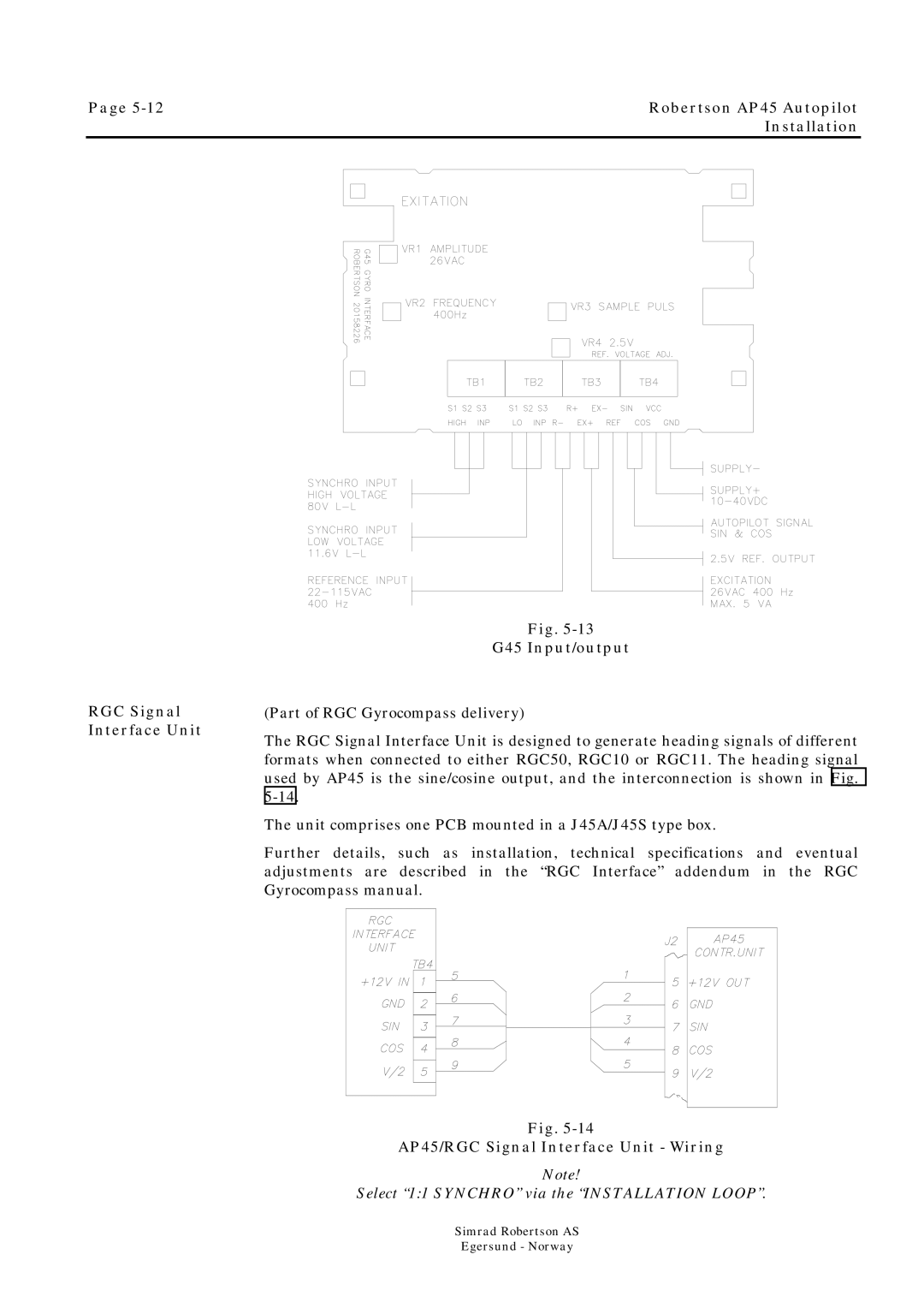
RGC Signal Interface Unit
Fig.
G45 Input/output
(Part of RGC Gyrocompass delivery)
The RGC Signal Interface Unit is designed to generate heading signals of different formats when connected to either RGC50, RGC10 or RGC11. The heading signal used by AP45 is the sine/cosine output, and the interconnection is shown in Fig.
The unit comprises one PCB mounted in a J45A/J45S type box.
Further details, such as installation, technical specifications and eventual adjustments are described in the “RGC Interface” addendum in the RGC Gyrocompass manual.
Fig.
AP45/RGC Signal Interface Unit - Wiring
Note!
Select “1:1 SYNCHRO” via the “INSTALLATION LOOP”.
Simrad Robertson AS
Egersund - Norway