Page | Robertson AP45 Autopilot |
| Trouble shooting |
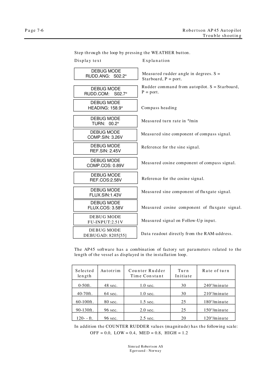
Step through the loop by pressing the WEATHER button.
Display text
DEBUG MODE
RUDD.ANG: S02.2°
DEBUG MODE
RUDD.COM: S02.7°
DEBUG MODE
HEADING: 158.9°
DEBUG MODE
TURN: 00.2°
DEBUG MODE
COMP.SIN: 3.26V
DEBUG MODE
REF.SIN: 2.45V
DEBUG MODE
COMP.COS: 0.89V
DEBUG MODE
REF.COS:2.58V
DEBUG MODE
FLUX.SIN:1.43V
DEBUG MODE
FLUX.COS: 3.58V
DEBUG MODE
FU-INPUT:2.51V
DEBUG MODE
DEBUGAD: 8205[55]
Explanation
Measured rudder angle in degrees. S = Starboard, P = port.
Rudder command from autopilot. S = Starboard, P = port.
Compass heading
Measured turn rate in ° /min
Measured sine component of compass signal.
Reference for the sine signal.
Measured cosine component of compass signal.
Reference for the cosine signal.
Measured sine component of fluxgate signal.
Measured cosine component of fluxgate signal.
Measured signal on
Data readout directly from the
The AP45 software has a combination of factory set parameters related to the length of the vessel as displayed in the installation loop.
Selected | Autotrim | Counter Rudder | Turn | Rate of turn |
length |
| Time Constant | Initiate |
|
|
|
|
|
|
48 sec. | 1.0 sec. | 30 | 240°/minute | |
64 sec. | 1.0 sec. | 30 | 210°/minute | |
80 sec. | 1.5 sec. | 25 | 180°/minute | |
96 sec. | 2.0 sec. | 25 | 150°/minute | |
120- - ft. | 96 sec. | 2.5 sec. | 20 | 120°/minute |
In addition the COUNTER RUDDER values (magnitude) has the following scale: OFF = 0.0, LOW = 0.4, MED = 0.8, HIGH = 1.2
Simrad Robertson AS
Egersund - Norway
