Robertson AP45 Autopilot | Page |
|
|
| 6. | ||
| After finishing the installation and interconnecting all units, check that correct | ||
| power and polarity is supplied to the junction unit. See page | ||
| Alignment and adaptation of the autopilot parameters to the vessel's | ||
| characteristics must be carried out according to the following procedure. | ||
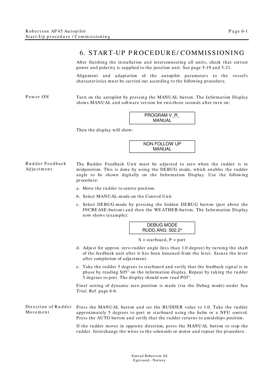
Power ON | Turn on the autopilot by pressing the MANUAL button. The Information Display | ||
| shows MANUAL and software version for | ||
|
|
|
|
|
| PROGRAM V_R_ |
|
|
| MANUAL |
|
| Then the display will show: | ||
|
|
| |
|
| NON FOLLOW UP |
|
|
| MANUAL |
|
Rudder Feedback Adjustment
The Rudder Feedback Unit must be adjusted to zero when the rudder is in midposition. This is done by using the DEBUG mode, which enables the rudder angle to be shown digitally on the Information Display. Use the following procedure:
a.Move the rudder to centre position.
b.Select
c.Select
DEBUG MODE
RUDD.ANG: S02.2°
S = starboard, P = port
Direction of Rudder Movement
d.Adjust for approx. zero rudder angle (less than 1.0 degree) by turning the shaft of the feedback unit after it has been loosened from the lever. Secure the lever after completion of adjustment.
e.Take the rudder 5 degrees to starboard and verify that the feedback signal is in phase by reading S05° on the information display. Repeat by taking the rudder 5 degrees to port. The display should now read P05°.
Final setting of dynamic zero position is made (via the Debug mode) under Sea Trial. Ref. page
Press the MANUAL button and set the RUDDER value to 1.0. Take the rudder approximately 5 degrees to port or starboard using the helm or a NFU control. Press the AUTO button and verify that the rudder returns to amidships position.
If the rudder moves in opposite direction, press the MANUAL button to stop the rudder. Interchange the wires to the solenoids or motor and repeat the procedure.
Simrad Robertson AS
Egersund - Norway
