Robertson AP45 Autopilot | Page |
Installation |
|
Unpacking and handling
General
AP45 Control Unit
5. INSTALLATION
Care should be taken when unpacking and handling the equipment. A visual inspection should be made to check that the equipment has not been damaged during shipment and that all components and parts are present according to the packing list.
Common sense should be used when installing the units, particular attention being given to the operator's need for ease of access.
For cable layout refer to the External Cabling Diagram, Fig.
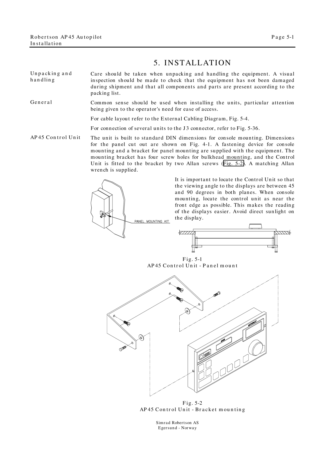
The unit is built to standard DIN dimensions for console mounting. Dimensions for the panel cut out are shown on Fig.
It is important to locate the Control Unit so that the viewing angle to the displays are between 45 and 90 degrees in both planes. When console mounting, locate the control unit as near the front edge as possible. This makes the reading of the displays easier. Avoid direct sunlight on the display.
Fig.
AP45 Control Unit - Panel mount
Fig.
AP45 Control Unit - Bracket mounting
Simrad Robertson AS
Egersund - Norway