Robertson AP45 Autopilot | Page |
Installation |
|
The different alternatives are described on page
Alternative 1: No resistor mounted.
Alternative 2: 1.0 Kohm (1/4W, 5 %)
Alternative 3: 3.0 Kohm (1/4W, 5 %)
Alternative 4: 5.1 Kohm (1/4W, 5 %)
Note!
If
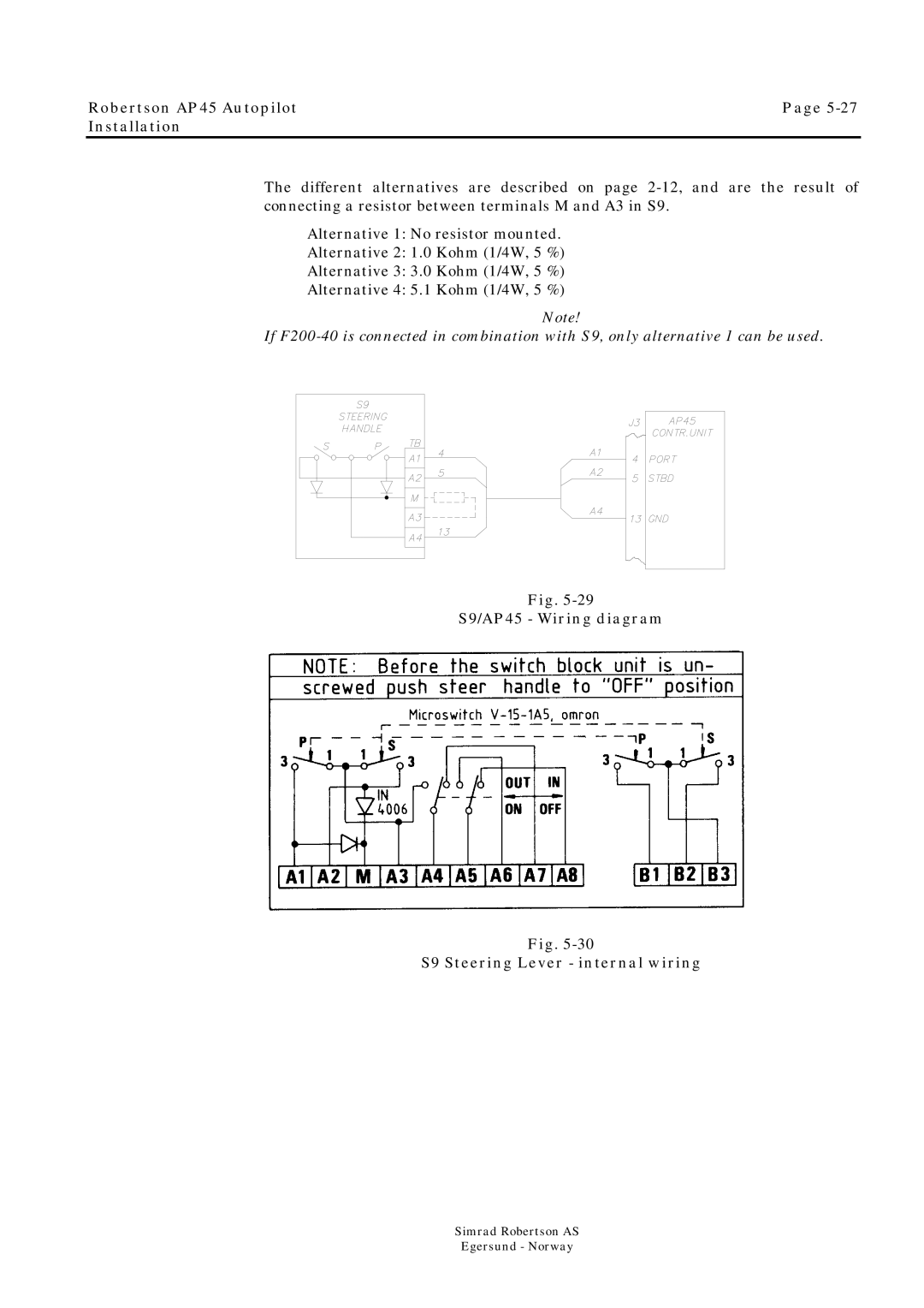
Fig.
S9/AP45 - Wiring diagram
Fig.
S9 Steering Lever - internal wiring
Simrad Robertson AS
Egersund - Norway