Robertson AP45 Autopilot | Page |
Spare parts and drawings |
|
|
|
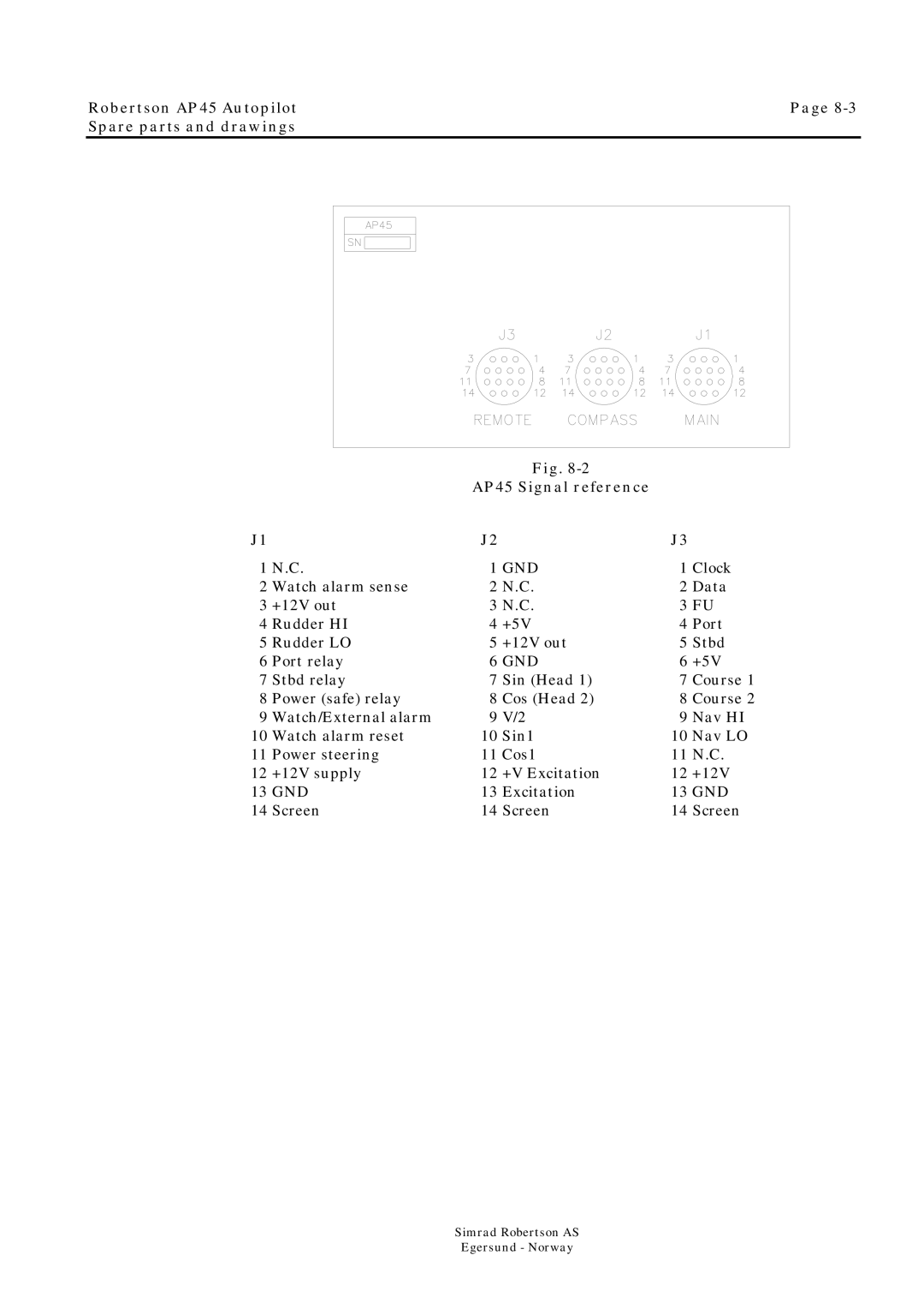
| Fig. |
|
|
|
| AP45 Signal reference |
|
| |
J1 |
| J2 |
| J3 |
|
1 N.C. | 1 GND | 1 Clock | |||
2 | Watch alarm sense | 2 | N.C. | 2 Data | |
3 | +12V out | 3 N.C. | 3 FU | ||
4 Rudder HI | 4 | +5V | 4 Port | ||
5 Rudder LO | 5 | +12V out | 5 Stbd | ||
6 Port relay | 6 GND | 6 | +5V | ||
7 | Stbd relay | 7 | Sin (Head 1) | 7 | Course 1 |
8 | Power (safe) relay | 8 | Cos (Head 2) | 8 | Course 2 |
9 | Watch/External alarm | 9 | V/2 | 9 | Nav HI |
10 Watch alarm reset | 10 Sin1 | 10 Nav LO | |||
11 | Power steering | 11 | Cos1 | 11 | N.C. |
12 | +12V supply | 12 | +V Excitation | 12 | +12V |
13 GND | 13 Excitation | 13 GND | |||
14 | Screen | 14 | Screen | 14 | Screen |
Simrad Robertson AS
Egersund - Norway
