Simrad ROBERTSON AP45 manual RF45X Internal Wiring RF45X Rudder Feedback Unit Mounting

Models: ROBERTSON AP45

1 124
Download 124 pages 5 Kb
Page 63
Image 63

Robertson AP45 Autopilot

Page 5-13

Installation


RF45X Rudder Feedback Unit

The RF45X is normally mounted with the shaft pointing upwards. It can, however, also be mounted with the shaft pointing downwards if that appears to be more convenient.

NOTE!

In case of an “upside-down” installation, the two plug-in straps on the component side of the PCB have to be “turned” 90° to achieve reversed output signal. (To remove the PCB from the housing, simply grip the potentiometer and pull.

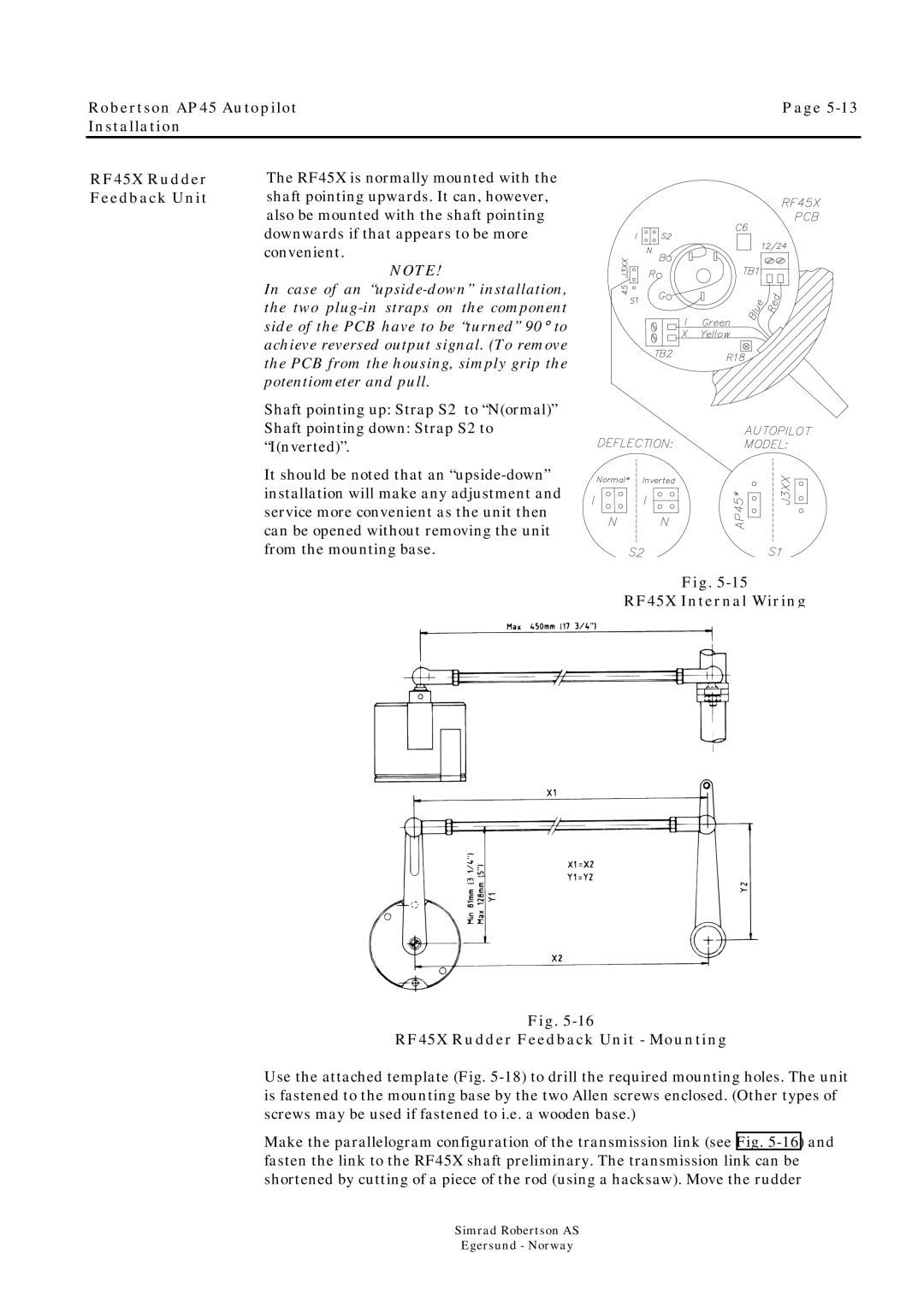
Shaft pointing up: Strap S2 to “N(ormal)”

Shaft pointing down: Strap S2 to “I(nverted)”.

It should be noted that an “upside-down” installation will make any adjustment and service more convenient as the unit then can be opened without removing the unit from the mounting base.

Fig. 5-15

RF45X Internal Wiring

Fig. 5-16

RF45X Rudder Feedback Unit - Mounting

Use the attached template (Fig. 5-18)to drill the required mounting holes. The unit is fastened to the mounting base by the two Allen screws enclosed. (Other types of screws may be used if fastened to i.e. a wooden base.)

Make the parallelogram configuration of the transmission link (see Fig. 5-16)and fasten the link to the RF45X shaft preliminary. The transmission link can be shortened by cutting of a piece of the rod (using a hacksaw). Move the rudder

Simrad Robertson AS

Egersund - Norway

Page 63
Image 63
Simrad ROBERTSON AP45 manual RF45X Internal Wiring RF45X Rudder Feedback Unit Mounting