Page
Table of Contents
HDCU-900, HD Camera Control Unit
File Structure
HDC-950/930, HD Color Video Camera
HDCU-950, HD Camera Control Unit
MSU-700A, Master Setup Unit
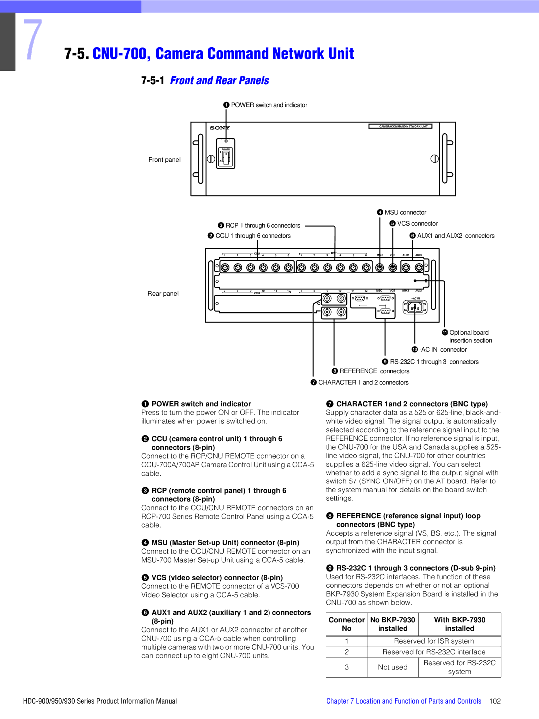
CNU-700, Camera Command Network Unit
CNU-500, Camera Command Network Unit
MSU-750, Master Setup Unit
Connector Panel
HDVF-C750W, HD Electronic Viewfinder
Hardware Software Camera characteristics
HDVF-C700W, HD Electronic Viewfinder
14.CA-905L, Large Lens Adaptor
HDC-900/950/930 Series Product Information Manual
Introduction
Advanced Digital Signal Processing Adsp
Overview
Sony Design Criteria
Electronic Shutter
Ergonomic Body Design
Optical Filter Wheels
Super EVS
Features of the System Components
High Definition Origination
Ntsc
Standard Definition Origination
Production Format
480/30P 576/50i
Total System
System Configuration
Studio Zoom Lens
Optional Accessories for the HDC-900
HDC-950 Stand-alone System
Frequency control
Camera Head
Skin tone detail function
Ratio control
Camera Control Unit
Control System
Viewfinders
Optional Accessories
For CNU/ MSU/RCP
System Setup
1Setting the System Format using HDCU-900
For HDCU-950
FC-83 board
RC/FC/LC
RC/LC
S805 S807 S806 S603
Required boards Slot to be installed
Top most slot DPR-163
HDCU-900
Second slot from the top FC-83
Third slot from the top RC-86 DIF-102 HDCU-900
ADA-59
System format DPR-163 board S804 Local
Setting switches
Combination of boards System format
FC-83 board RC-86
SD Component SDI Return Video Signal
SDI-54A
IF-789A VDA-57
RC/FC/LC RC/LC
Setting switches Switch setting System format DPR-163 board
RC/FC
FC-83 board LC-41 RC-86 S804 Local
Required boards
Remarks
RC-86 DIF-102 HDCU-900 Third slot from the top LC-41
Switch setting System format DPR-163 board
LC-41 RC-86 S804 Local
SD Sync OUT Refrence
Setting the frame conversion when the Hkcu Is installed
Setting the HD-SDI output
Setting the SD signal output
HDCU-950
Combination of boards Board name Slot
DTX-1 DRX-1
HIF-5
2-2Standard HD/SD System
SD Analog Monitor Waveform Monitor
2-3HD/SD Film Like System
Picture Monitor
VBS OUT Analog Composite Video Signal
2-4Analog NTSC/PAL System
Rack Mounting of System Equipment
Mounting the unit using the RMM-30 Rack Mount Rail
When a 1U unit is mounted
Inch size equipment
Fasten the screws loosened in step
Installation
Rack at the screw holes at 31.75 mm
Pull the rails out
Carefully
Required Parts
RCP-700 Series and MSU-700 Series
Digital Signal Processing
Normal
Full DSP Camera Processing
Multi Matrix
Normal HDC-900/950/930 Series Product Information Manual
Precise Handling of Highlight Position
Low key saturation
With conventional cameras, low light areas can be
Triple Skin Tone Detail Correction
Normal CH-2 On Sharper
CH-1 On
Adaptive Detail Control
Electronic Soft Focus
Outstanding reliability and easy maintenance
Low power consumption
Control System
Standard switch
Sony Camera Command Network System
Extended Technical Access to Camera Video Processing
Easy operation
Character display
Camera Command Network Units CNU-700 and CNU-500
Emergency feature
CNU-700 CNU-500
Height Inch standard rack
Power supply to RCP
CCU
Mauntable
HDC-900
HDC-900 HDCU-900 Down Con VCS-700 Outputs
Multi-MSU Operation Example
Supervisory MSU
New Remote Control Panels RCP-750/751
Operation Panel of the RCP-750/751
Extremely Flexible Configuration
Auto Set-up
BUS Control
Controlling the router from an MSU panel
Controlling the router from an RCP
Controlling the RCP assignment from other S-Bus equipment
Serial Tally Transfer
Decodes S-Bus serial tally signal and forward to Hdcu
Camera name display onto CNU
CNU-700 requires a BKP-7933 option for S-Bus functionality
Optical Fiber Connector and Cable
Female connector
Cleaning of the Connector and Cable
Male connector
Optical Fiber Overview
Damage the alignment sleeve
Alignment sleeve Sony P/N
Quick Lesson on Camera Settings
Camera adjustment
One-touch power on
Setup
Stable time
1-1To set a new security code
Initial Settings for the Control System
1Specifying the Security Code
Color matching between the cameras
1-2To change the security code
1-3To enable to cancel the security code
Press Engineer Mode
Press Code Change
2Setting the Security Status
MSU-700A
Operation
Each digit you input will be displayed as an
Setting the status for control from the MSU-700A
3MSU Assignment
Press MSU Assign
4Setting the Operating Conditions of the MSU
3-1To restore operations of the MSU- 700A/750
To resume the initial assignment
When the clock setting is completed
4-1To display the MSU Configuration menu
4-3To adjust the buzzer sound
4-2To set the built-in clock
4-4To turn on/off the buzzers independently
4-6To adjust the brightness of the LEDs
4-7To adjust the brightness of the EL display
4-5To turn off all the buzzers
File Structure
Location and Function of Parts and Controls
HDC-900, HD Color Video Camera
1Right Side and Left Side Panels
Prompter connector BNC type
Accessory bracket
Microphone power switches
Test OUT test signal output connector BNC type
Video signal select buttons
When a color viewfinder is used
Power indicator
Screen Size Marker switch
CC color temperature conversion filter selector
VF viewfinder Scan switch
Center Marker switch
Memory Stick media card section
Es Intercom 1 and 2 connectors XLR 5-pin
Back tally lamp
Return Select knob
HDC-950/930, HD Color Video Camera
1Front Right Side
2Front Left Side
3Back Left Side
EXT I/O external input and output connector 20-pin
Audio in audio input 1, 2 connectors BNC type and switches
DC in DC power supply input connector XLR 4-pin
DC OUT DC power supply output connector Pin
Power switch
INCOM1 and 2 controls and switches
HDCU-900, HD Camera Control Unit
1Front Panel
Power supply is turned off with the CAM PW button
Position turns the power on, and setting it to turns it
It off. When a remote control panel is connected
RCP/CNU Remote connector 8-pin
3HD Signal Input/Output Block
WF OUT waveform monitor output connector BNC type
Sync OUT HD/SD sync signal output connector BNC type
PIX OUT picture monitor output connector BNC type
WF Mode waveform monitor mode connector 4-pin
But do not operate when the system field frequency is 60 Hz
Sync OUT SD sync signal output connector BNC type
Sync OUT HD/SD sync signal output connectors BNC type
Sync OUT HD sync signal output connector BNC type
PIX OUT HD picture monitor output connector BNC type
7HKCU-903 Frame Rate Converter Unit
9Internal Boards DPR board
HDCU-950, HD Camera Control Unit
10Internal Boards AT board
Reference connectors BNC type
Intercom volume control
Intercom connector XLR 5-pin Connect a headset
Intercom line selector
MIC Remote microphone remote connector D-sub 15-pin
RET4 return video input 4 connector
Moni HD-SDI monitor output connector BNC type
WF Mode waveform monitor mode output Connector 4-pin
5HKCU-953 HD Frame Rate Converter Unit
4HKCU-951 SD Encoder Unit
6Internal Switches and Internal
Boards Internal switches Boards AT Board
8Internal Switches and Internal
Boards AVP Board Boards DTX Board
Boards DRX Board
Convert indicator
Sync To adjust the sync level
SC Phase switch
Frame indicators
CNU-700, Camera Command Network Unit
1Front and Rear Panels
CNU-500, Camera Command Network Unit
Mode switch 0 Factory setting
+5 V indicator
Operation switch
Through F Not used UP/DOWN switch
VCS-700, Video Selector
MSU-700A, Master Setup Unit
1Operation Panel
Close iris close button
VF PW viewfinder power button
Auto Setup block
Standard button
IC card insertion block
Scene file control block
Menu operation block
To insert a card
Camera select block
Picture Monitor buttons
Waveform Monitor buttons
Filter control block
4 ND
Shutter mode when the ECS button is not lit
Clear
Examples
AC in AC power input connector
3Connector Panel
Menu operation block/1 Mode mode select buttons
2Operation Panel in use with HD Equipment
MSU-750, Master Setup Unit
Signal output select buttons
Auto Level START/ White Black HUE Break
Monitor output select buttons
Connector does not change. By lighting both
Connector that corresponds to the lit
Button. The output signal from the other
Panel Para Expand Active
ECS/SHUTTER Gamma Master ND CC
Access IC Memory Card
Display window block
ND filter Examples 1 Clear
Iris
Extauto
Manual
RCP-750/751, Remote Control Panel
10-1Operation Panel
Power and output signal select block
White white balance manual adjustment knobs
Alarm indicator
Control select block
Level Start White
Memory Stick media card slot and access lamp
So that it goes dark
Break
10-2Iris/master black control block RCP-750
Not lit
Absolute mode
Relative button
Master Black control
Iris gauge
10-4Connector Panel
AUX Remote auxiliary remote connector Pin
White line on the gauge provides a click position
Parts common to the RCP-700/701
RCP-700/701, Remote Control Panel
11-1Operation Panel
Items a through m are common to the RCP-700 and RCP-701
Black black balance button
Black black balance manual adjustment knobs
Iris control lever/preview switch
Coarse control knob
Connector
Preview button
12-1Operation Panel
Shutter control block
Filter
Paint control block
White balance control block
Standard button green illumination
Iris/master black control block Black balance control block
Active button green illumination
VTR control block
Monitor connector BNC
12-2Connector Panel
Camera connector 8-pin
Output selector
Setting Contents Gory
Settings on the RM Configuration Menu
To make settings on the menu
To select the Basic menu
RM-B750, Hand-held Remote Control Unit
13-1Operation Panel
Memory Stick slot
Rewind button
Close button
VTR START/STOP button
Fast forward button
13-2Connector Panel
Iris/master black control block
White balance/black balance control block
HDVF-20A, HD Electronic Viewfinder
14-1Appearance
HDVF-700A, HD Electronic Viewfinder
15-1Appearance
Tally ON/OFF switch
Peaking switch
Friction adjustment knob
Batt battery indicator
HDVF-C700W/C750W, HD Electronic Viewfinder
Friction adjustment/lock lever
Contrast control*1 Adjusts the picture contrast
16-1Appearance
Peaking control*1
Blanking marker ON/OFF switch
Tally dimmer switch
Green tally lamps
17-1Lens Attachment Section Front and Connectors
17.CA-905L, Large Lens Adaptor
Viewfinder Saddle
17-3Rear control panel
Connectors and Cables
HDC-950/930 Connector Layout
1Connector Input/Output Signals
HDC-900 Connector Layout
CCD Black Adaptor
Earphone OUT HDC-950/930 Earphone mini jack Test OUT
CCU connector
Signal Specifications
Prompter OUT
Intercom CH1/CH2 5P Female
Remote 8P Female AC OUT HDC-900
Audio in CH1/CH2 3P Female
DC in 4P Male
Qf VTR 26P Male HDC-950/930
Lens 36P Female HDC-900
Signal
Qg Lens 12P Female HDC-950/930, HKC-T950
VF 25P Female HDC-900
VF 20P Female HDC-950/930
EXT I/O 20P HDC-950/930
Qk Tracker Female
MIC HKC-T950
Signal Specifications Incom HKC-T950
Front MIC 3P Female HDC-950/930
HKC-T950
OPT Head HKC-T950
CAM Body HKC-T950
2Wiring Diagrams for Cables
Indication Connection connector/cable
1-1BNC connector
1-2CAMERA connector optical/electrical connector
Recall system*4 Signal Specifications
1735HD/1730HD*4 Signal Specifications
Male
1-6TRUNK Line D-sub 9-pin, Female
1-9WF Mode 4-pin, Female
1-8INTERCOM/TALLY/PGM D-sub 25-pin Female
1-7I/O Port D-sub 15-pin, Female
Connector Connector/cable
2Cable Wiring Diagram
3Connection Connectors
1-11INTERCOM 5-pin, Female 1-10RCP/CNU 8-pin, Female
Digital signal HD SDI OUT 1 to 2 BNC
Digital signal RET 1 to 3 in BNC
SD 525/625 digital signal RET 1 to 3 in BNC
Serial OUT 1 to 2, Moni BNC
1-4MIC Remote D-sub 15-pin, Female
Composite connector
1-3MIC1/MCI2 XLR 3-pin, Male
8pin
1-7RCP/CNU 8-pin, Female
2Connection Connectors
WF Mode 4-pin, Female
1-8INTERCOM 5-pin, Female
1-1BNC connector 75 Ohms
1-2RS232C-1/2/3*19P, Female
1-3REMOTE 8P, Female
3Connection Connector
Connector name
1-2RS232C 9P, Female
AUX Remote auxiliary remote connector 8- pin
2Cable Wiring
Connector name Connection connector/cable
BNC VCS
INPUT/OUTPUT PORT*1
Power +
Spare Chassis GND
INPUT/OUTPUT Port *1
1Connector Panel
Remote CCU/CNU
2Connection Connector
Connector function Connection connector
Pin Signal Specifications
HDVF-C700W, HD Electronic Viewfinder
HDVF-C750W, HD Electronic Viewfinder
13-1-2Remote 8P, Female
13-1Connector Input/Output Signals
WF Mode 4P, Female
13-1-3I/O Port D-SUB 37P, Female
14-1-2LENS 12P, Male
14-1Connector Input/Output Signals
14-1-1REMOTE 8P, Male
14-1-3LENS 36P, Female
14-1-5VF 25P, Female BKP-9057
HD video Pin Signal Specifications
14-1-4VF 20P, Male BKP-9057
SD video
SD video Pin Signal Specifications
Glossary Terms and Definitions
Hardware
Knee point and knee slope
Knee aperture
Knee correction
Level depend
Software
Camera characteristics
Specifications
Output connectors
Optical system specifications
Input connectors
Supplied accessories
HDC-950, HD Color Video Camera
Optional accessories BKP-L551 Battery Adaptor
HDC-930, HD Color Video Camera
Pin 1, 10.5 to 17 V DC
INCOM/TALLY/PGM
WF Mode
Camera
RCP/CNU Remote Trunk Line Port
RCP/CNU
HD-SDI SMPTE-292M
HD SDI OUT
SD SDI OUT
CCA-5-10 Connection Cable 10 meter/33 feet
Supplied accessories Input and output connectors
Character Input
Inputs/outputs
Remote connectors
Supplied accessory Optional accessories
AUX
RM-B150 front panel, Hand-held Remote Control Unit
RM-B750 front panel, Hand-held Remote Control Unit
Scanning Format
Input voltages and signal characteristics
Deflection and high voltage
Lines
TALLY/G TALLY/BATT
Color temperature 6500K Indicators
Input signals
Pb,Pr 7Vp-p, asynchronous Terminated
CCD block adaptor I/F
Supplied accessories Optional accessories
10-19.CA-905L, Large Lens Adaptor
Cable adaptor I/F
Appendix
Function comparison chart Paint
MSU-700A MSU-750 RCP-750/751 RM-B750 Menu
Control Item Menu
Shutter
Menu Direct
ECS/S-EVS
ECS EVS
Function comparison chart File
Function comparison chart Maintenance
Black Set Gain Bounce on Off B, Master
C,D,E
Function comparison chart Configuration
CNU RCP
Detail
Black RCP
Flare
LCD
Function comparison chart Function
MSU-700A MSU-750 RCP-750/751 RM-B750 Menu Control Item
ECS
Function comparison chart Multi, Card
Function comparison chart Button and Knob
Button MSU-700A MSU-750 RCP-750/751 RM-B750
Panel Active
VF Disp VF Menu Cancel Enter
Iris Relative
VTR START/STOP Stop REW Play REC Review Monitor