E6581090
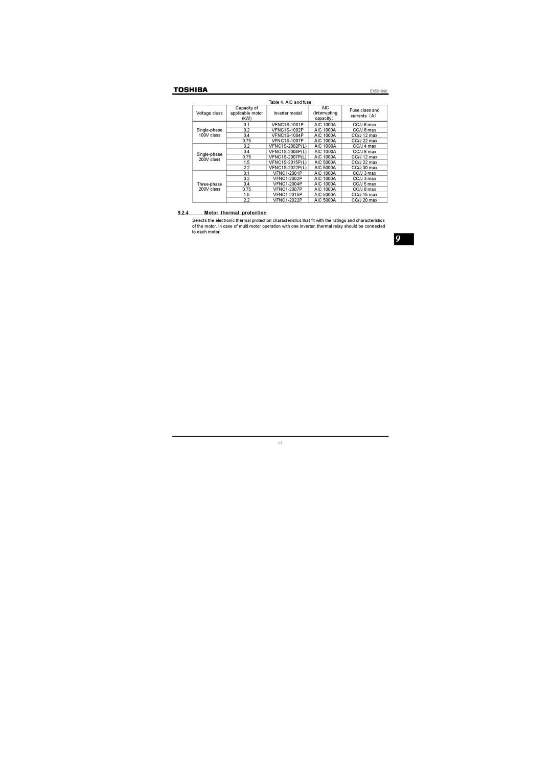
Table 4. AIC and fuse
| Capacity of |
| AIC | Fuse class and | |
Voltage class | applicable motor | Inverter model | (Interrupting | ||
currents(A) | |||||
| (kW) |
| capacity) | ||
|
|
| |||
0.1 | AIC 1000A | CC/J 6 max | |||
0.2 | AIC 1000A | CC/J 8 max | |||
100V class | 0.4 | AIC 1000A | CC/J 12 max | ||
| 0.75 | AIC 1000A | CC/J 22 max | ||
| 0.2 | AIC 1000A | CC/J 4 max | ||
0.4 | AIC 1000A | CC/J 8 max | |||
0.75 | AIC 1000A | CC/J 12 max | |||
200V class | |||||
1.5 | AIC 5000A | CC/J 22 max | |||
| |||||
| 2.2 | AIC 5000A | CC/J 30 max | ||
| 0.1 | AIC 1000A | CC/J 3 max | ||
0.2 | AIC 1000A | CC/J 3 max | |||
0.4 | AIC 1000A | CC/J 5 max | |||
200V class | 0.75 |
| AIC 1000A | CC/J 8 max | |
| 1.5 | AIC 5000A | CC/J 15 max | ||
| 2.2 | AIC 5000A | CC/J 20 max |
9.2.4Motor thermal protection
Selects the electronic thermal protection characteristics that fit with the ratings and characteristics of the motor. In case of multi motor operation with one inverter, thermal relay should be connected to each motor.
9
