E6581090
9.1.5Compliance with Low voltage directive
Please carry out the below mentioned countermeasures for the Low Voltage Directive in case of using
(1)Inverter should be installed in a panel. Pay attention to wiring openings, so that it should prevent someone from touching live parts through the opening in case of maintenance.
(2)No more than 1 cable should be connected to one earth terminal of the main terminal board. In this case, other cables for ground should be grounded on the metal back plate and/or in the cubicle. The
9
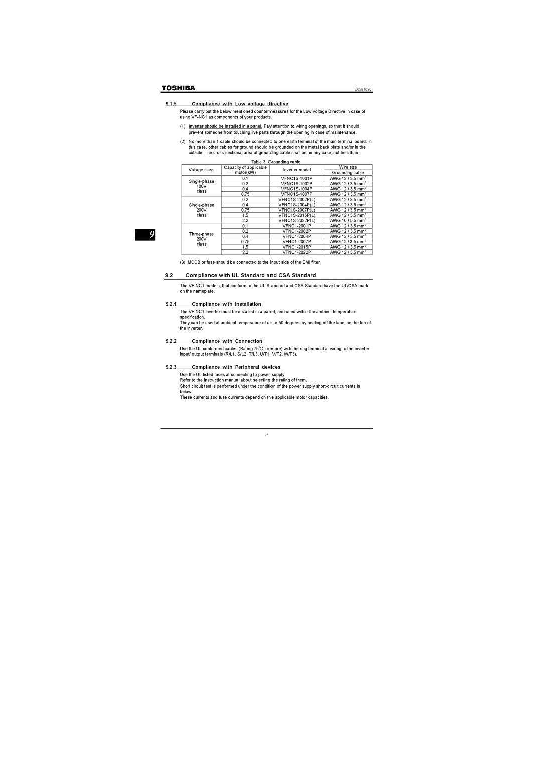
Table 3. Grounding cable
Voltage class | Capacity of applicable | Inverter model | Wire size | |
motor(kW) | Grounding cable | |||
|
| |||
0.1 | AWG 12 / 3.5 mm2 | |||
0.2 | AWG 12 / 3.5 mm2 | |||
100V |
|
|
| |
0.4 | AWG 12 / 3.5 mm2 | |||
class |
|
|
| |
0.75 | AWG 12 / 3.5 mm2 | |||
0.2 | AWG 12 / 3.5 mm2 | |||
0.4 | AWG 12 / 3.5 mm2 | |||
200V | 0.75 | AWG 12 / 3.5 mm2 | ||
class | 1.5 | AWG 12 / 3.5 mm2 | ||
| 2.2 | AWG 10 / 5.5 mm2 | ||
| 0.1 | AWG 12 / 3.5 mm2 | ||
0.2 | AWG 12 / 3.5 mm2 | |||
0.4 | AWG 12 / 3.5 mm2 | |||
200V |
|
|
| |
0.75 |
| AWG 12 / 3.5 mm2 | ||
class |
|
|
| |
1.5 | AWG 12 / 3.5 mm2 | |||
| 2.2 | AWG 12 / 3.5 mm2 |
(3)MCCB or fuse should be connected to the input side of the EMI filter.
9.2Compliance with UL Standard and CSA Standard
The
9.2.1Compliance with Installation
The
They can be used at ambient temperature of up to 50 degrees by peeling off the label on the top of the inverter.
9.2.2Compliance with Connection
Use the UL conformed cables (Rating 75℃ or more) with the ring terminal at wiring to the inverter input/ output terminals (R/L1, S/L2, T/L3, U/T1, V/T2, W/T3).
9.2.3Compliance with Peripheral devices
Use the UL listed fuses at connecting to power supply.
Refer to the instruction manual about selecting the rating of them.
Short circuit test is performed under the condition of the power supply
These currents and fuse currents depend on the applicable motor capacities.