E6581090
10.2Installation of a magnetic contactor
If using the inverter without installing a magnetic contactor (MC) in the primary circuit, use an MCCB (with a power cutoff device) to open the primary circuit when the inverter protective circuit is activated.
■Magnetic contactor in the primary circuit
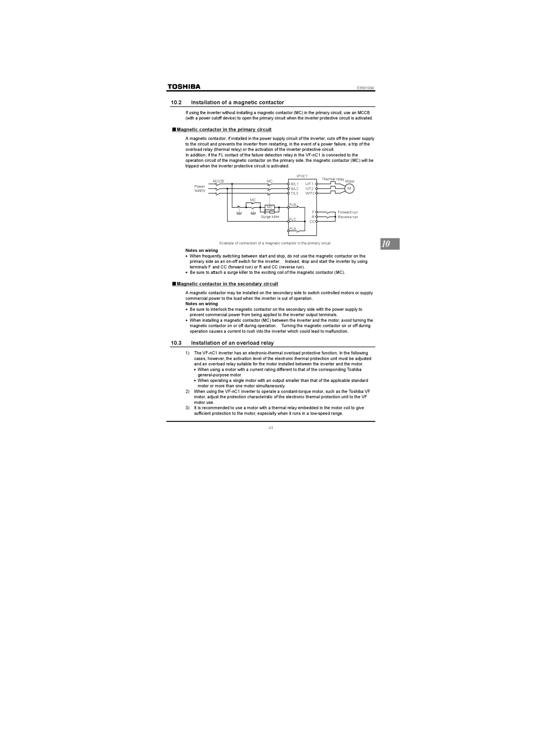
A magnetic contactor, if installed in the power supply circuit of the inverter, cuts off the power supply to the circuit and prevents the inverter from restarting, in the event of a power failure, a trip of the overload relay (thermal relay) or the activation of the inverter protective circuit.
In addition, if the FL contact of the failure detection relay in the
|
| VFnC1 | Thermal relay Motor | |
MCCB | MC | R/L1 | U/T1 | |
Power |
| IM | ||
| S/L2 | V/T2 | ||
supply |
| |||
| T/L3 | W/T3 |
| |
|
|
| ||
| MC |
|
|
|
| MC | FLB |
|
|
|
|
|
| |
| Surge killer |
| F | Forward run |
| FLC | R | Reverse run | |
|
| CC |
| |
|
|
|
| |
|
| FLA |
|
|
Example of connection of a magnetic contactor in the primary circuit | 10 |
|
Notes on wiring
•When frequently switching between start and stop, do not use the magnetic contactor on the primary side as an
•Be sure to attach a surge killer to the exciting coil of the magnetic contactor (MC).
■Magnetic contactor in the secondary circuit
A magnetic contactor may be installed on the secondary side to switch controlled motors or supply commercial power to the load when the inverter is out of operation.
Notes on wiring
•Be sure to interlock the magnetic contactor on the secondary side with the power supply to prevent commercial power from being applied to the inverter output terminals.
•When installing a magnetic contactor (MC) between the inverter and the motor, avoid turning the magnetic contactor on or off during operation. Turning the magnetic contactor on or off during operation causes a current to rush into the inverter which could lead to malfunction.
10.3Installation of an overload relay
1)The
•When using a motor with a current rating different to that of the corresponding Toshiba
•When operating a single motor with an output smaller than that of the applicable standard motor or more than one motor simultaneously
2)When using the
3)It is recommended to use a motor with a thermal relay embedded in the motor coil to give sufficient protection to the motor, especially when it runs in a