E6581090
14.2Periodical inspection
Make a periodical inspection at intervals of 3 or 6 months depending on the operating conditions.
![]() Danger
Danger
•Before inspection, perform the following steps.
| ①Shut off all input power to the inverter. |
Mandatory | ②Wait for at least 15 minutes and check that the charge lamp is no longer lit. |
| ③Use a tester that can measure DC voltages (800V DC or more), and check that the |
| voltage to the DC main circuits (across |
| Performing an inspection without carrying out these steps first could lead to electric shock. |
•Never replace any part.
This could be a cause of electric shock, fire or bodily injury. To replace parts, call the local
Prohibited | sales agency. |
■Check items | |
1. | Check to see if all screwed terminals are tightened firmly. | If any screw is found loose, tighten it | |
|
| again with a screwdriver. |
|
2. | Check to see if all crimped terminals are fixed properly. | Check them visually to see that there | |
|
| is no trace of overheating around any of them. |
|
3. | Check visually all cables and wires for damage. |
| |
4. | With a vacuum cleaner, remove dirt and dust, especially from the vents and the printed circuit | ||
|
| boards. Always keep them clean to prevent an accident due to dirt or dust. | |
5. | When leaving the inverter unused for a long time, check it for functioning once every 2 years or | ||
|
| so by supplying it with electricity for at least 5 hours with the motor disconnected. It is | |
|
| advisable not to supply the commercial power directly to the inverter but to gradually increase | |
|
| the power supply voltage with a transformer. |
|
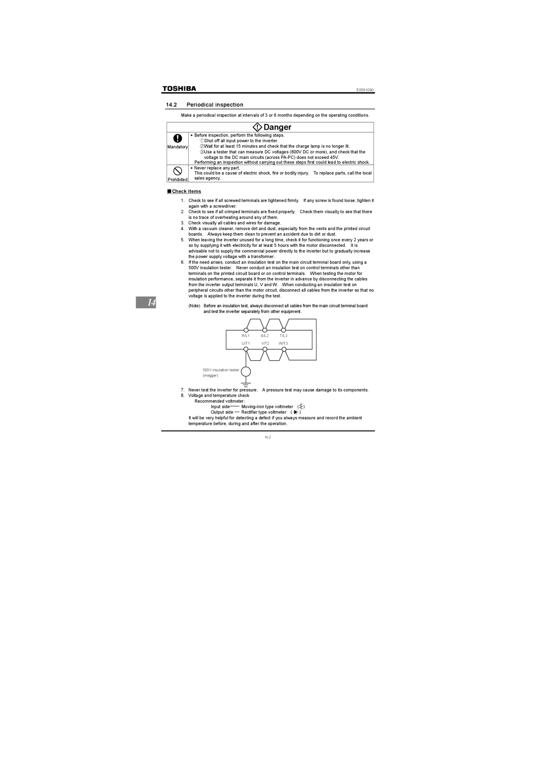
6. | If the need arises, conduct an insulation test on the main circuit terminal board only, using a | ||
|
| 500V insulation tester. Never conduct an insulation test on control terminals other than | |
|
| terminals on the printed circuit board or on control terminals. When testing the motor for | |
|
| insulation performance, separate it from the inverter in advance by disconnecting the cables | |
|
| from the inverter output terminals U, V and W. When conducting an insulation test on | |
|
| peripheral circuits other than the motor circuit, disconnect all cables from the inverter so that no | |
|
| voltage is applied to the inverter during the test. |
|
14 |
|
| |
| (Note) Before an insulation test, always disconnect all cables from the main circuit terminal board | ||
and test the inverter separately from other equipment.
|
|
|
|
|
R/L1 | S/L2 | T/L3 |
| |
U/T1 | V/T2 | W/T3 |
| |
|
|
|
|
|
|
|
|
|
|
500V insulation tester (megger)
7.Never test the inverter for pressure. A pressure test may cause damage to its components.
8.Voltage and temperature check
Recommended voltmeter: |
|
| ||
Input side____ | ( ) | |||
Output side __ | Rectifier type voltmeter ( |
|
| ) |
It will be very helpful for detecting a defect if you always measure and record the ambient temperature before, during and after the operation.