E6581090
1.3Name and function of each part
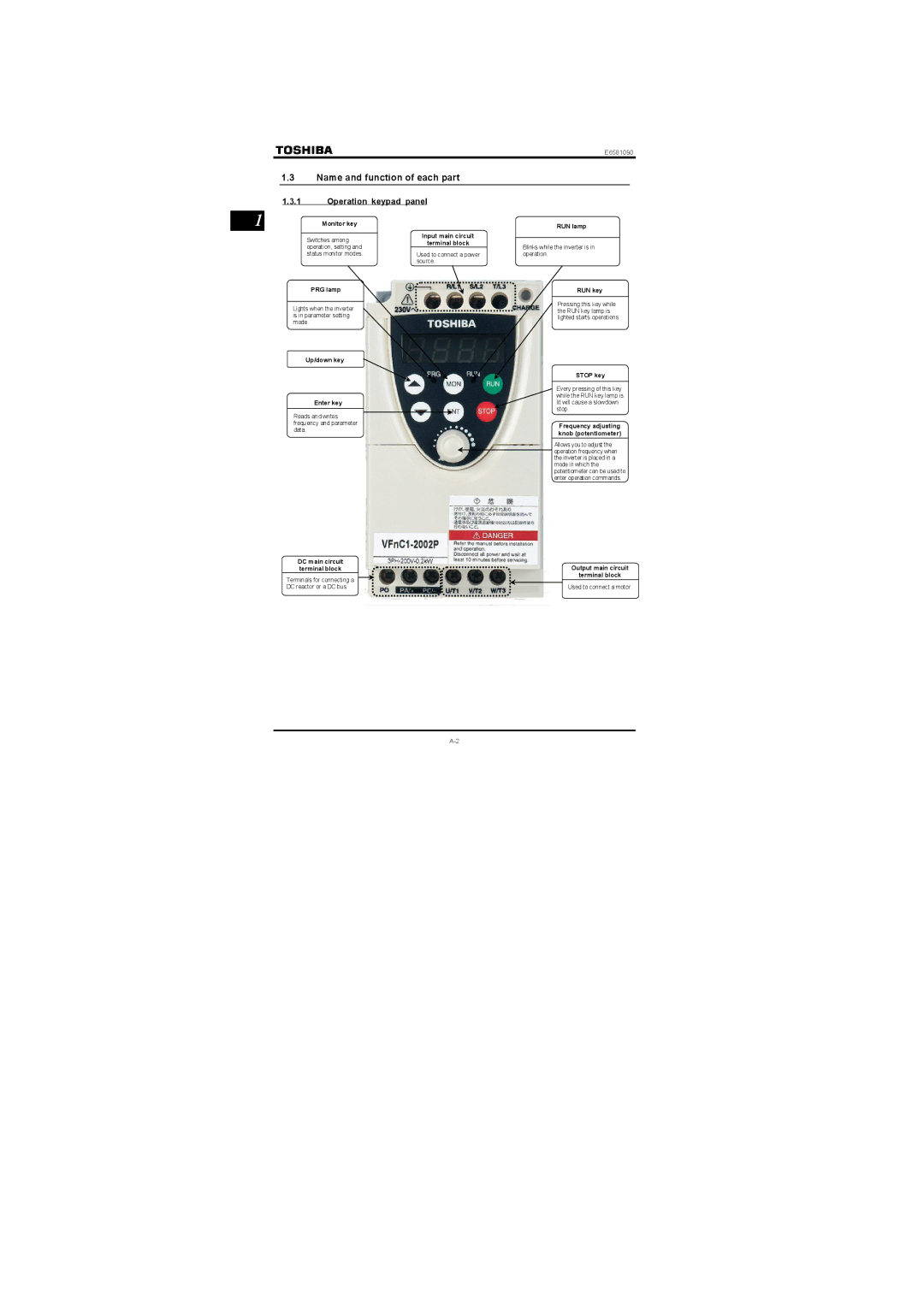
1.3.1Operation keypad panel
1 | Monitor key |
Switches among operation, setting and status monitor modes.
PRG lamp
Lights when the inverter is in parameter setting mode.
Up/down key
Enter key
Reads and writes frequency and parameter data.
Input main circuit terminal block
Used to connect a power source.
RUN lamp
Blinks while the inverter is in operation.
RUN key
Pressing this key while the RUN key lamp is lighted starts operations.
STOP key
Every pressing of this key while the RUN key lamp is lit will cause a slowdown stop.
Frequency adjusting knob (potentiometer)
Allows you to adjust the operation frequency when the inverter is placed in a mode in which the potentiometer can be used to enter operation commands.
DC main circuit |
| Output main circuit | ||
terminal block |
| |||
Terminals for connecting a |
|
|
| terminal block |
|
|
|
| |
DC reactor or a DC bus |
| Used to connect a motor. | ||