E6581090
10. Peripheral devices
Danger
•When using wiring materials and their optional devices for the inverter, they must
| be installed in a cabinet. |
Mandatory | Failure to do so can lead to risk of electric shock and can result in death or serious |
| injury. |
•Connect earth cables securely. Failure to do so can lead to risk of electric shock
or fire in case of a failure,
Be Grounded
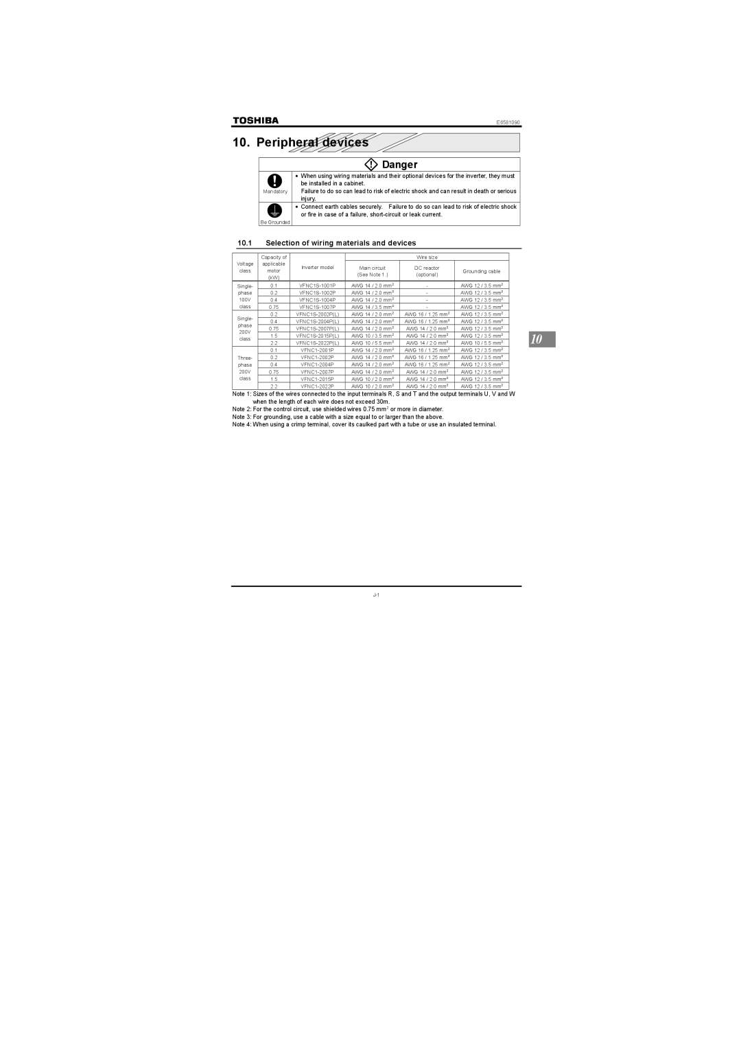
10.1Selection of wiring materials and devices
Voltage
class
Capacity of applicable motor (kW)
Inverter model
| Wire size |
| |
Main circuit | DC reactor | Grounding cable | |
(See Note 1.) | (optional) | ||
| |||
|
|
|
Single- | 0.1 | AWG 14 / 2.0 mm2 | - | AWG 12 / 3.5 mm2 |
|
| |
phase | 0.2 | AWG 14 / 2.0 mm2 | - | AWG 12 / 3.5 mm2 |
| ||
100V | 0.4 | AWG 14 / 2.0 mm2 | - | AWG 12 / 3.5 mm2 |
|
| |
class | 0.75 | AWG 14 / 3.5 mm2 | - | AWG 12 / 3.5 mm2 |
|
| |
Single- | 0.2 | AWG 14 / 2.0 mm2 | AWG 16 / 1.25 mm2 | AWG 12 / 3.5 mm2 |
|
| |
0.4 | AWG 14 / 2.0 mm2 | AWG 16 / 1.25 mm2 | AWG 12 / 3.5 mm2 |
|
| ||
phase | 0.75 | AWG 14 / 2.0 mm2 | AWG 14 / 2.0 mm2 | AWG 12 / 3.5 mm2 |
|
| |
200V | 1.5 | AWG 10 / 3.5 mm2 | AWG 14 / 2.0 mm2 | AWG 12 / 3.5 mm2 |
| 10 | |
class |
|
|
|
|
|
| |
2.2 | AWG 10 / 5.5 mm2 | AWG 14 / 2.0 mm2 | AWG 10 / 5.5 mm2 |
| |||
|
| ||||||
| 0.1 | AWG 14 / 2.0 mm2 | AWG 16 / 1.25 mm2 | AWG 12 / 3.5 mm2 |
|
| |
Three- | 0.2 | AWG 14 / 2.0 mm2 | AWG 16 / 1.25 mm2 | AWG 12 / 3.5 mm2 |
|
| |
phase | 0.4 | AWG 14 / 2.0 mm2 | AWG 16 / 1.25 mm2 | AWG 12 / 3.5 mm2 |
|
| |
200V | 0.75 | AWG 14 / 2.0 mm2 | AWG 14 / 2.0 mm2 | AWG 12 / 3.5 mm2 |
|
| |
class | 1.5 | AWG 10 / 2.0 mm2 | AWG 14 / 2.0 mm2 | AWG 12 / 3.5 mm2 |
|
| |
| 2.2 | AWG 10 / 2.0 mm2 | AWG 14 / 2.0 mm2 | AWG 12 / 3.5 mm2 |
|
| |
Note 1: Sizes of the wires connected to the input terminals R, S and T and the output terminals U, V and W when the length of each wire does not exceed 30m.
Note 2: For the control circuit, use shielded wires 0.75 mm2 or more in diameter.
Note 3: For grounding, use a cable with a size equal to or larger than the above.
Note 4: When using a crimp terminal, cover its caulked part with a tube or use an insulated terminal.
