A p p l e T a l k / S e r i a l I n t e r f a c e B o a r d |
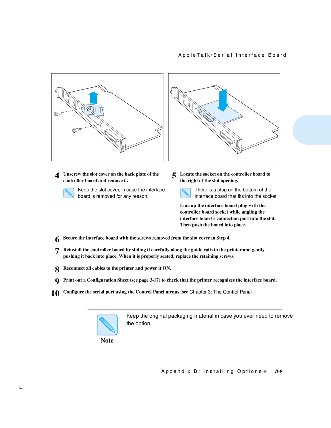
4 Unscrew the slot cover on the back plate of the | 5 Locate the socket on the controller board to |
controller board and remove it. | the right of the slot opening. |
Keep the slot cover, in case the interface board is removed for any reason.
There is a plug on the bottom of the interface board that fits into the socket.
Line up the interface board plug with the controller board socket while angling the interface board’s connection port into the slot. Then push the board into place.
6
7 Reinstall the controller board by sliding it carefully along the guide rails in the printer and gently pushing it back into place. When it is properly seated, replace the retaining screws.
8
9
10
Reconnect all cables to the printer and power it ON.
Print out a Configuration Sheet (see page
Configure the serial port using the Control Panel menus (see Chapter 3: The Control Panel).
Keep the original packaging material in case you ever need to remove
the option.
Note
A p p e n d i x B : I n s t a l l i n g O p t i o n s ❖