SuperStack II PathBuilder S330/S310
95052-8145
3Com Corporation
Bayfront Plaza
Santa Clara, California
Contents
Configuring In-band Management
Getting Started
Configuring CTX Buffers
166
151 Common VIrtual Circuit Parameters
151
OC3/STM-1 Port Virtual Circuit Parameters 151
Viewing OC3/STM-1 ATM Statistics
Viewing T1/E1 UNI Card Statistics 186
187 T1/E1 Group Statistics 188
189
237
214 Serial Interface Frame Protocol Modes ATM DXI Mode 215
219
219 Ethernet Interface 222 Bridge Operation 223
Rack Mounting
Servicing
Cords
Power and Power
Canadian CS-03
FCC Part 68 Statement
Approval Information
CE Notice
Managing PathBuilder products
Where to Find Specific Information
Introduction
Specific information, and describes guide conventions
List conventions that are used throughout this guide
Conventions
Related
Documentation
PathBuilder S330/S310 Overview
PathBuilder S330 Features
System Description
Single T1/E1 UNI
PathBuilder S310 WAN Access Switch
Software downloading via TFTP, FTP, or direct via RS232
Specifications are subject to change without notice
Specifications
PathBuilder S330 System Specifications
Management Interface
Standards
T1 / n x E1 Interface
Ethernet Interface
Serial Interface
OC3/STM-1 Interface
PathBuilder S330 System Specifications
RTS
RTS CTS
AAL1, ATM CES
DCD
Voice Compression Module Specifications
PathBuilder S310 System Specifications
PIN 6 DSR
T1/E1 UNI Interface
PathBuilder S310 System Specifications
RTS
RTS CTS
CBR Module Specifications
RTS
Voice Compression Module Specifications
Part Number Description
PathBuilder S310 Part Numbers
Part Number
Ancillary Items
Inspecting PathBuilder S330/S310
Receiving
General Installation Procedure
PathBuilder S330 Full System Configuration
PathBuilder S310 Full System Configuration
Unit
S330/S310 chassis
PathBuilder S330/S310 supports three optional modules
Voice Compression Module Connections
Removing the PathBuilder S330/S310 Cover
Installing the Optional Modules in the Unit
Removing the Cover Plate from Slot
Replacing the PathBuilder S330/S310 Cover
Replace the unit’s cover
To connect AC or DC power, follow these steps
Connect AC or DC Power and optionally the RPS System
AC/DC Source Specifications
Shelf Fill for AC/DC Power Application
Installing the Optional RPS System
Illustrates the power supply socket and fuse
Shows the port configuration of a PathBuilder S330/S310
Connecting to the Serial Port
Connecting to the T1/E1 UNI Interface
Following tables describe the serial port connector pinouts
Shorting GR 53, 54, 55
Frame GND Circuit GND 15, 16 19, 20
RTS CTS
Shorting GR 47, 48
DCD not used, see Out DCE cable
Shorting GR
PathBuilder S330/S310 Serial Port LEDs
PathBuilder S330/S310 Ethernet Port LEDs
Connecting to the Ethernet Port
OC3/STM-1 UNI Multi-Mode Fiber Optic Cable
Connecting to the OC3/STM-1 Port
CBR T1-DSX/E1 Pinouts
Connecting to the CBR Module
Lists the CBR V.35/RS-366 Y cable pinouts
CBR V.35/RS-366 Connector Pinouts
Lists the VCM T1-DSX pinouts
Connecting to the Voice Compression Module
VCM T1-DSX/E1 Pinouts
Voice Compression Module Leds
Connecting to the DS3/E3 Module
DS3 UNI Module LEDs
Network Management Station Terminal Connection Options
Logging On
For details about connecting the VT100 terminal
PathBuilder S330/S310 Main Menu
Main menu, shown in , appears
Using the Menus
Set ATM Payload Scramble
Change Settings select
Manage Card
Configuration Management
System Configuration
Performing Initial
System Clock Configuration Menu
Manage IP Network Configuration Menu
Configuring the Local Host IP Address
Shows a sample PathBuilder S330/S310 IP host setup
Trap Client Configuration Menu
Configuring Trap Clients
Default Gateway Configuration Menu
Configuring the Default Gateway
Time and Date Configuration Menu
Date
Super User Privilege Menu
Following prompt appears at the bottom of the screen
Press any key to resume your session in read-write mode
Getting Started
Configuring In-band Management
Getting Started
Configuring System
Viewing
Information
Specifying General System Information
Report Firmware Version Screen
Version
Page
Downloading via the Serial Port
Downloading via the Ethernet Port
Equipment List
Configuration
Using
Management Menu
Shapers. To display the Mcpu Menu, follow these steps
Menu
Configuring
Management CPU
Mcpu Configuration Menu
Viewing Mcpu Configuration Information
Mcpu Shaper Screen
CTX Menu
CTX Shapers Menu
Enter the desired buffer size, in cells 256 cells = 1 block
Select 1 Set Buffer Size. The following prompt appears
Configuring Ports
Setting Congestion Thresholds
Interface
Configuring the T1/E1
Ports
T1 DS1 UNI Port Selection Menu
Activation/Deactivation Bit Error Rates
Adding UNI Groups
Bit Error Rates Translated into Total Number of Errors
Bit Error Rate Total Errors
UNI groups
Add Group Menu Selecting Group Type
Select 1 UNI. The Add Group menu appears as shown in Figure
Add Group Menu Adding UNI Group
Adding IMA Groups
Select 2 IMA. The Add Group menu appears as shown in Figure
Add Group Menu Adding IMA Group
If desired, repeat steps 5-8 to set up another IMA group
Change any of the group parameters as desired
Viewing and Modifying IMA and UNI Groups
Deleting IMA and UNI Groups
Delete Group Menu
State Tx Condition Rx Condition
Possible IMA Link States
Possible IMA LInk Failure Status Conditions
Status
Failure Description
Group Status Selection Menu
# Tx Configured Links-The number of configured transmit links
Configuring the T1/E1 Card
From the Configuration Management menu, shown in , select
Change certain settings
OC3/STM-1 Port
To configure the OC3/STM-1 port, follow these steps
Menu. shows the DS3 UNI Configuration menu. The E3 UNI
DS3/E3 UNI Module
Configuration menu is similar
Configuring the serial card
Received Plcp
CTX Timing Source-The CTX timing source for the DS3/E3 port
Configuring the serial port
SIM Configuration Port/Card Selection Menu
Port
Configuring the Serial Port
SIM LMI Configuration Menu
Configuring
Configuring the Ethernet Interface
Configuring the Ethernet Interface
Configuring the Ethernet Card
Manage Bridge Menu
Bridge Menu
Configuring Source Protocol Filtering
Source Protocol Filter Menu
Configuring Source Address Filtering
Enter 2 to enable the source protocol filter
Source Address Filter Menu
Enter 2 to enable the source address filter
Destination Address Filter Menu
Configuring Destination Address Filtering
Viewing the List Forwarding Table
Enter 2 to enable the destination address filter
Bridge Static Table Menu
Constructing the Bridge Static Table
Enabling and Disabling the Spanning Tree
Enter 1 or 2 to disable or enable the Spanning Tree
Configuring the CBR
Module
CBR E1 Port Configuration Menu Unstructured Mode
Port Mode-The type of service configured to the specified port
Page
Illustrates the Srts and Adaptive timing options
Serial Port
DS0 Trunk Conditioning
Configuring the CBR Serial Port
Page
Enter the number of the channel you want to configure
Channels
VCM Channel Configuration Menu
T1/E1 Port
VCM Configuration Menu
Page
VCM Card Configuration Menu
Card
Virtual Circuit Menu
Selecting the Virtual Circuit Class
Initial Add Virtual Circuit Screen
Selecting the PVC Virtual CIrcuit Type VCC or VPC
Circuits
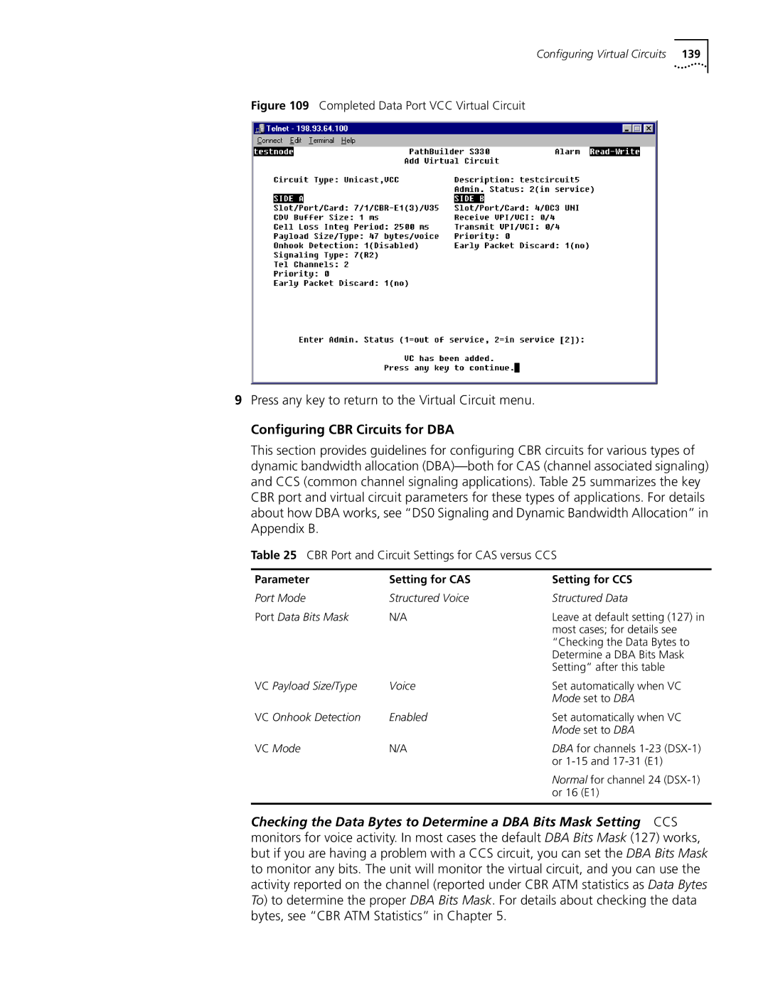
Configuring Virtual Circuits
Add Virtual Circuit Screen with Side a Completed
Press any key to return to the Virtual Circuit menu
CBR Port and Circuit Settings for CAS versus CCS
Configuring CBR Circuits for DBA
Set the Port Mode to Structured Voice
Set the Port Mode to Structured Data
Page
Configuring Virtual Circuits
Completed RS366 video Virtual Circuit Template
Compression Module VCC Circuits
VCM VCC Add Virtual Circuit Screen with Side a Completed
Completed VCM VCC Virtual Circuit
DLCI-Enter the number of the Dlci to be used for the circuit
Completed VCM Subchannel Circuit
VCM Subchannel Virtual Circuit Example
At PathBuilder S330 B S330 B
At PathBuilder S330 a S330 a
At PathBuilder S330 C S330 C
OC3/STM-1 Port Virtual Circuit Parameters
Common VIrtual Circuit Parameters
Mcpu Virtual Circuit Parameters
T1/E1 UNI Port Virtual Circuit Parameters
Service
Translation Encapsulation Mode
CBR Module Virtual Circuit Parameters
Ethernet Port Virtual Circuit Parameters
Configuring Virtual Circuits
Steps
Voice Compression Module Virtual Circuit Parameters
Or group
Viewing Virtual Circuits for the Entire Chassis
Shows a representative List Virtual Circuit detail screen
List Virtual Circuit Detail Screen
Viewing Virtual Circuits by Port or Group
Virtual Circuits
Access Virtual Circuits by Port/Group Screen
To display the Manage Video Dial menu
Dial Feature
Managing the Video
Routing table
Starting Video Dial-up Sessions
Sessions
Manually Disconnect a Site Menu
Ending Video Dial-up Sessions
Video Call Routing Table
Page
Current Alarms
Alarms
Managing System
Select 2 Clear Current Alarms
Mcpu and CTX Module System Alarms
Mcpu and CTX Module System Alarms
Alarm Meaning Troubleshooting Steps
Super user has changed a Information only By Super User
Alarms Common to Several Modules
Alarms Common to Several Interfaces
Alarm Meaning
Line, or the port configuration
DS1/E1 UNI Module Alarms
Config. Abort is generated
DS1/E1 UNI Module Alarms Meaning Troubleshooting Steps
Managing System Alarms
ATM Forum R-123
Alarm Meaning Troubleshooting Steps
Describes the alarms specific to DSX-1 and E1 CBR modules
DSX-1/E1 CBR Module Alarms
DSX-1/E1 CBR Module Alarms
Qsim Alarms
SIM Alarms
Describes the alarms specific to QSIMs and FAMs
Voice Compression Module Alarms
Clearing History Alarms
Viewing and Printing History Alarms
Return to the Fault Management menu
Management menu shown earlier in Figure
Using Loopbacks
Points should help you identify and resolve the problem
These steps
OC3/STM-1 Loopback Menu
Illustrates the loopbacks for OC3/STM-1
Illustrates the loopbacks for the E3 module
Setting VCM Channel Loopbacks
Setting VCM Port Loopbacks
VCM Channel Loopback Menu
ATM Statistics
Viewing Performance
Statistics
This section describes the T1/E1 port/link statistics
T1/E1 Port/Link Statistics
This section describes the T1/E1 group statistics
T1/E1 Group Statistics
Viewing OC3/STM-1 Performance Statistics
Card Statistics
Pathbuilder S330 Diagnostics and Performance Statistics
Viewing OC3/STM-1 ATM Statistics
To view DS3 UNI performance statistics, follow these steps
Viewing DS3 UNI Performance Statistics
Viewing DS3 UNI ATM Statistics
Viewing E3 UNI ATM Statistics
Viewing E3 UNI Performance Statistics
SIM Frame Relay Statistics
SIM Hdlc Statistics
SIM ATM VC Statistics
Ethernet Statistics screen displays the following statistics
Ethernet Statistics
Spanning Tree Statistics
Ethernet Statistics
CBR Performance Monitoring Statistics
CBR ATM Statistics
VCM Card Statistics Menu
Voice Compression Module Performance Monitoring Statistics
Voice Compression Module Port Activity Statistics
Viewing Virtual Circuit
Statistics
Voice Compression Module VC Statistics
Row 1 left to right
Statistics by Circuit
Statistics by Port/Group
Row 2 left to right
Statistics by Shaper
Virtual Circuit Statistics by Shaper Summary Screen
Statistics by Buffer Queue
3Com FTP Site
Services
Online Technical
World Wide Web Site
408 727
Access by Analog Modem
Access by Digital Modem
408 654
North America
Country Telephone Number Asia Pacific Rim
Europe
Latin America
Country Telephone Number Fax Number
CTX Switch
CTX Buffers Menu Displaying Default Memory Allocation
, for details about setting up virtual circuits
Carrying AAL5 traffic
VPI and VCI Ranges
PathBuilder S310 does not include an OC3/STM-1 port
For intermediate range operation up to 15 kilometers
Serial Interface Frame
Serial Interface
Protocol Modes
PathBuilder S330/S310 to ATM PVC
ATM DXI Mode
AAL
DCE Allows DTE to Participate in ATM Network through ATM DXI
Shows the applications for DXI
Frame Relay Mode
HDLC/SDLC Mode
Service Interworking Function
Network Interworking Function
Managing traffic Handling congestion
Ethernet Interface
Ethernet segments over ATM WAN
Filtering
Spanning Tree operates as follows
Spanning Tree Operation
Addressing
Spanning Tree Instances
Virtual Circuit Scheme
Virtual Circuits in a Switched Network
Segmentation
Reassembly
PathBuilder S330/S310 Application
ATM Bridging
Emulation compliant device
CBR Module
Page
CBR Structured DS1 Drop and Insert
Structured DS0 Combining
DS0 Signaling and Dynamic Bandwidth Allocation
Illustrates AAL1 structured DS1
Page
Structured versus Unstructured Summary
When to use Structured Versus Unstructured Service
Unstructured
Structured Versus Unstructured Effects on Transit DS1
Point-to-Point Video Conferencing
Destination # Tx vpi/vci Rx vpi/vci Speed Status
Multi-point Video Conferencing
Source Tx vpi/vci Rx vpi/vci DSOs
VCM supports the following features
Numbers
Symbols
CRC-4126, 132 CTS&DCD option 128 CTX
IMA
245
238, 239 port
247
Index
3Com Corporation Limited Warranty
Disclaimer