Shelf Fill for AC/DC Power Application
Installing the Optional RPS System
Illustrates the power supply socket and fuse
Shows the port configuration of a PathBuilder S330/S310
Connecting to the Serial Port
Connecting to the T1/E1 UNI Interface
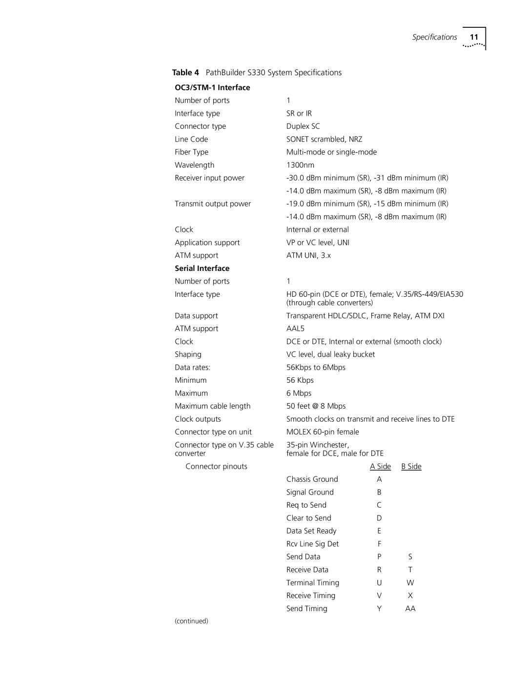
Following tables describe the serial port connector pinouts
Shorting GR 53, 54, 55
Frame GND Circuit GND 15, 16 19, 20
RTS CTS
Shorting GR 47, 48
DCD not used, see Out DCE cable
Shorting GR
PathBuilder S330/S310 Serial Port LEDs
PathBuilder S330/S310 Ethernet Port LEDs
Connecting to the Ethernet Port
OC3/STM-1 UNI Multi-Mode Fiber Optic Cable
Connecting to the OC3/STM-1 Port
CBR T1-DSX/E1 Pinouts
Connecting to the CBR Module
Lists the CBR V.35/RS-366 Y cable pinouts
CBR V.35/RS-366 Connector Pinouts
VCM T1-DSX/E1 Pinouts
Connecting to the Voice Compression Module
Lists the VCM T1-DSX pinouts
Voice Compression Module Leds
Connecting to the DS3/E3 Module
DS3 UNI Module LEDs
Network Management Station Terminal Connection Options
Logging On
For details about connecting the VT100 terminal
PathBuilder S330/S310 Main Menu
Main menu, shown in , appears
Using the Menus
Set ATM Payload Scramble
Change Settings select
Manage Card
Configuration Management
System Configuration
Performing Initial
System Clock Configuration Menu
Manage IP Network Configuration Menu
Configuring the Local Host IP Address
Shows a sample PathBuilder S330/S310 IP host setup
Trap Client Configuration Menu
Configuring Trap Clients
Default Gateway Configuration Menu
Configuring the Default Gateway
Time and Date Configuration Menu
Date
Super User Privilege Menu
Following prompt appears at the bottom of the screen
Press any key to resume your session in read-write mode
Getting Started
Configuring In-band Management
Getting Started
Information
Viewing
Configuring System
Specifying General System Information
Report Firmware Version Screen
Version
Page
Downloading via the Serial Port
Downloading via the Ethernet Port
Equipment List
Management Menu
Using
Configuration
Shapers. To display the Mcpu Menu, follow these steps
Menu
Configuring
Management CPU
Mcpu Configuration Menu
Viewing Mcpu Configuration Information
Mcpu Shaper Screen
CTX Menu
CTX Shapers Menu
Enter the desired buffer size, in cells 256 cells = 1 block
Select 1 Set Buffer Size. The following prompt appears
Configuring Ports
Setting Congestion Thresholds