Chapter 1: Overview | June 30, 2006 | ||
| Table | ||
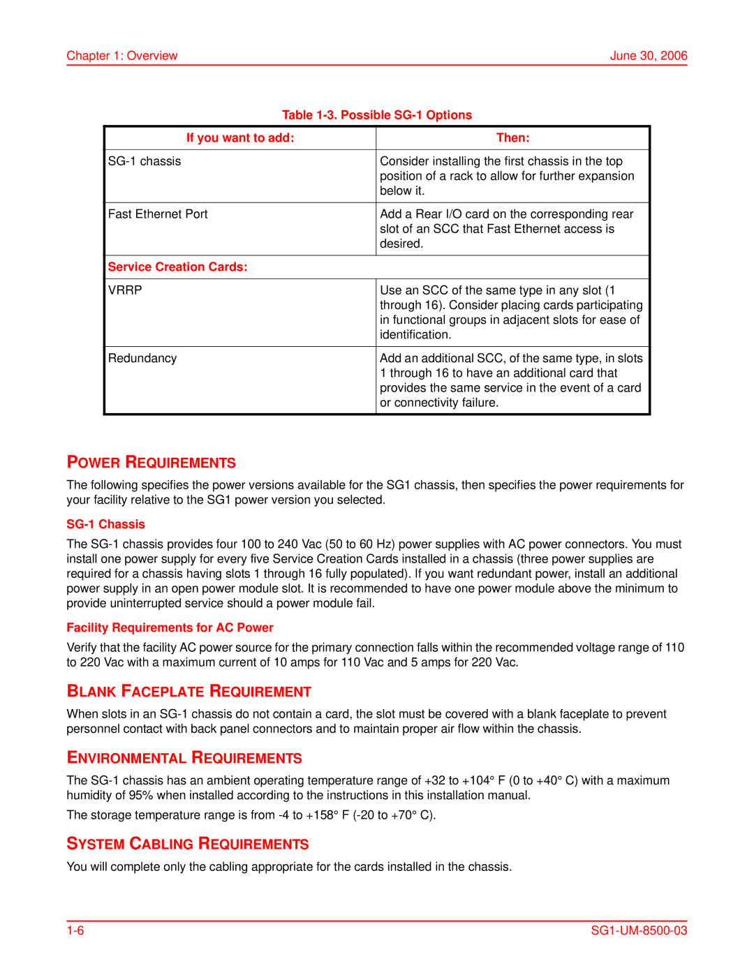
| If you want to add: | Then: |
|
|
|
|
|
| Consider installing the first chassis in the top |
| |
|
| position of a rack to allow for further expansion |
|
|
| below it. |
|
|
|
|
|
| Fast Ethernet Port | Add a Rear I/O card on the corresponding rear |
|
|
| slot of an SCC that Fast Ethernet access is |
|
|
| desired. |
|
|
|
|
|
| Service Creation Cards: |
|
|
|
|
|
|
| VRRP | Use an SCC of the same type in any slot (1 |
|
|
| through 16). Consider placing cards participating |
|
|
| in functional groups in adjacent slots for ease of |
|
|
| identification. |
|
|
|
|
|
| Redundancy | Add an additional SCC, of the same type, in slots |
|
|
| 1 through 16 to have an additional card that |
|
|
| provides the same service in the event of a card |
|
|
| or connectivity failure. |
|
|
|
|
|
POWER REQUIREMENTS
The following specifies the power versions available for the SG1 chassis, then specifies the power requirements for your facility relative to the SG1 power version you selected.
SG-1 Chassis
The
Facility Requirements for AC Power
Verify that the facility AC power source for the primary connection falls within the recommended voltage range of 110 to 220 Vac with a maximum current of 10 amps for 110 Vac and 5 amps for 220 Vac.
BLANK FACEPLATE REQUIREMENT
When slots in an
ENVIRONMENTAL REQUIREMENTS
The
The storage temperature range is from
SYSTEM CABLING REQUIREMENTS
You will complete only the cabling appropriate for the cards installed in the chassis.