Appendix A: MSTP Overview
Instances: CIST 0 |
|
|
| BPDU Packet |
|
Port 1 | (Default VLAN) | Port 3 (Blocked) |
Switch A
plus |
| plus |
Switch B | ||
|
|
(VLAN 3) | 2719 |
|
Port 6 | BPDU Packet |
| Port 8 | |
| Instances: CIST 0 and MSTI 15 |
|
| |
|
|
| ||
|
|
|
|
|
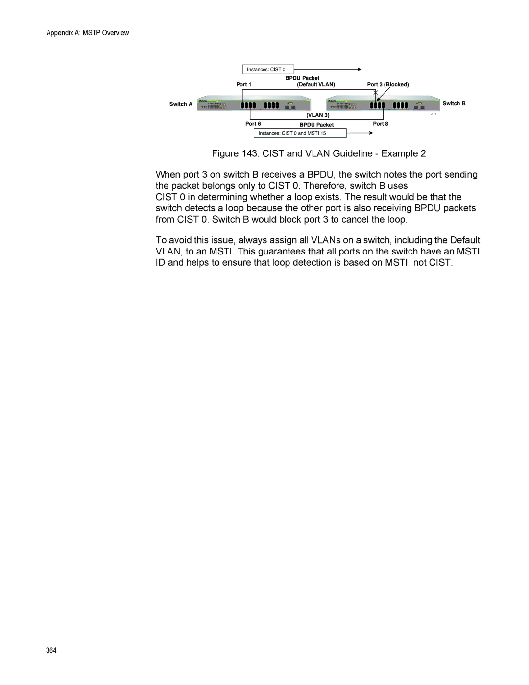
Figure 143. CIST and VLAN Guideline - Example 2
When port 3 on switch B receives a BPDU, the switch notes the port sending the packet belongs only to CIST 0. Therefore, switch B uses
CIST 0 in determining whether a loop exists. The result would be that the switch detects a loop because the other port is also receiving BPDU packets from CIST 0. Switch B would block port 3 to cancel the loop.
To avoid this issue, always assign all VLANs on a switch, including the Default VLAN, to an MSTI. This guarantees that all ports on the switch have an MSTI ID and helps to ensure that loop detection is based on MSTI, not CIST.
364