AT-GS950/16PS
Copyright 2013 Allied Telesis, Inc
Contents
101
Ingress Rate Limiting 143 Egress Rate Limiting
202
258
Displaying System Information 307 Setting Port States
Management Login Dialog Box
List of Figures
Figures
Dhcp Snooping Vlan Settings 296
Figures
List of Tables
List of Tables
Preface
Document Conventions
Allied Telesis Contact Information
Preface
Getting Started
Section
Page
Starting a Web Browser Session
Chapter
Switch’s IP Address
Snmp
Lldp
Web Browser Tools
Quitting a Web Browser Management Session
System Configuration
System Management Information
AT-GS950/16PS Switch Web Interface User’s Guide
Configuration of IP Address, Subnet Mask and Gateway Address
AT-GS950/16PS Switch Web Interface User’s Guide
IP Access List Configuration
Create an IP Access List
Delete an IP Address List Entry
User Name and Password Configuration
Add New User Name Password
Modify User Name Password
Delete User Name and Password
User Interface Configuration
User Interface Timeout
Manually Setting System Time
System Time
System Configuration
Setting Daylight Savings Parameters
Daylight Savings Time Status field, select Enabled
SSL Settings
AT-GS950/16PS Switch Web Interface User’s Guide
Dhcp and ATI Web Discovery Tool
Dhcp Client Configuration
System Configuration
Dhcp Auto Configuration
System Information Display
AT-GS950/16PS Switch Web Interface User’s Guide
System Log Configuration
System Log Configuration
AT-GS950/16PS Switch Web Interface User’s Guide
System Configuration
Bridge Configuration
Page
Port Configuration
Overview
Displaying and Configuring Ports
Port Configuration
AT-GS950/16PS Switch Web Interface User’s Guide
Port Configuration
STP and Rstp
Overview
Bridge Priority Root
Increment Bridge Priority
Path Costs and Port Costs
Forwarding Delay Topology Changes
Step
Hello Time and Bridge Protocol Data Units Bpdu
Mixed STP and Rstp Networks
Point-to-Point Ports
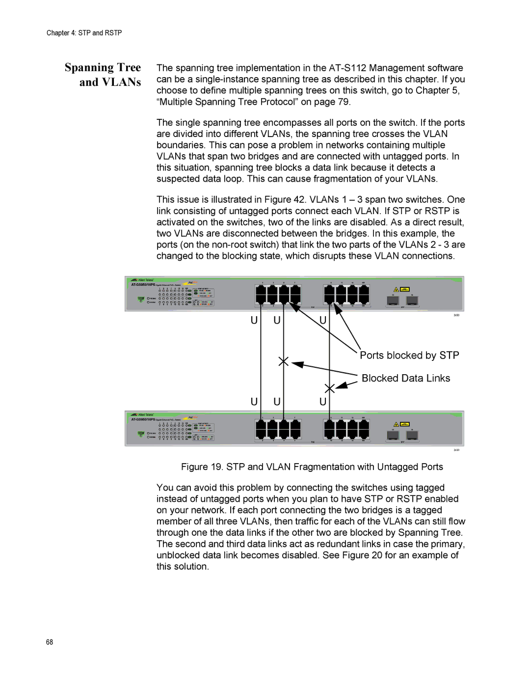
Spanning Tree and VLANs
Ports blocked by STP Blocked Data Links
Page
Basic STP and Rstp Configuration
Rapid Spanning Tree Configuration
AT-GS950/16PS Switch Web Interface User’s Guide
STP and Rstp
Configure Rstp Port Settings
Configure Basic Rstp Port Settings
STP and Rstp
Configure Advanced Rstp Port Settings
AT-GS950/16PS Rstp Advanced Port Configuration
STP and Rstp
AT-GS950/16PS Switch Web Interface User’s Guide
Spanning Tree Topology
From the Spanning Tree folder, select Topology Info
Multiple Spanning Tree Protocol
Multiple Spanning Tree Configuration
AT-GS950/16PS Switch Web Interface User’s Guide
Multiple Spanning Tree Protocol
Port Configuration
From the Mstp folder, select Mstp Port Configuration
Multiple Spanning Tree Protocol
AT-GS950/16PS Switch Web Interface User’s Guide
Vlan Mapping
Open Mstp Vlan Mapping Create Vlan Mapping to MST Instance
Modify MST Instance Delete MST Instance
Port Settings
AT-GS950/16PS Switch Web Interface User’s Guide
Topology Information
AT-GS950/16PS Switch Web Interface User’s Guide
Multiple Spanning Tree Protocol
Static Port Trunking
Static Trunk
General Guidelines
Static Port Trunking
Create a Port Trunk
Static Port Trunking
Modify a Port Trunk
100
Disable a Port Trunk
Static Port Trunking 102
Lacp Port Trunks
104
System Priority
Port Priority Value
General Guidelines
108
Group Status
Configuration Example
111
Port Priority Configuration
From the Trunk Config folder, select Port Priority
Port Mirroring
114
Port Mirroring Configuration
116
Disable Port Mirroring
Port Mirroring 118
Loopback Protection
Configuration
121
Status
MAC Address Table
124
125
Static Unicast MAC Address Configuration
127
Modify Static Unicast Address
Delete Static Unicast Address
Static Multicast Address Configuration
131
132
Modify Static Multicast Address
Delete Static Multicast Address
Igmp Snooping
136
137
Igmp Snooping Configuration
139
Igmp Snooping 140
Storm Control
142
Ingress Rate Limiting Egress Rate Limiting
Configuration
From the Storm Control folder, select Storm Control
145
Ingress Rate Limiting
For a partial view of this
147
Egress Rate Limiting
Virtual LANs
Vlan Overview
Port-based Vlan Overview
Vlan Name
Tagged Vlan Overview
General Rules for Creating a Port-based Vlan
Tagged and Untagged Ports
General Rules for Creating a Tagged Vlan
Assign Ports to a Vlan Mode
156
Tagged Vlan Configuration
Create a Tagged
Modify a Tagged
AT-GS950/16PS Modify Vlan
Delete a Tagged
161
Tagged Vlan Port Settings
163
Port-Based Vlan Configuration
Create a Port- Based Vlan
Modify a Port- Based Vlan
166
Gvrp
Overview and Guidelines
General Configuration
From the Gvrp folder, select Gvrp Global Configuration
Enable The Restricted Vlan Registration is active for
171
Time Settings
173
Gvrp 174
Quality of Service and Cost of Service
176
Egress Queue vs Packet Priority Mapping
Ieee 802.1p Port Priority
Scheduling
Prioritizing Untagged Packets
Weighted Round Robin Priority Scheduling
Port Egress Queue Maximum Number
Mapping CoS Priorities to Egress Queues
CoS
181
Associate Ports to CoS Priorities
Associate Dscp Classes to Egress Queues
184
Queue Scheduling Algorithm
Quality of Service and Cost of Service 186
Advanced Features
188
SNMPv1 and v2c
SNMPv1 and SNMPv2c Overview
Trap Receiver Attributes
Activate Snmp Interface
SNMPv1 and SNMPv2c User and Group Names
Create User and Group Names
Modify User and Group Names
Snmp User/Group Page Example
Delete User and Group Names
Enter a new Community Name
Snmp Community Strings
Create Snmp Community Strings
Modify Snmp Community Strings Delete Snmp
From the Snmp folder, select Trap Management
Snmp Traps
Create Trap Host Table Entry
Modify a Trap Host Table Entry
Delete a Trap Host Table Entry
200
SNMPv3
SNMPv3 Authentication Protocols
SNMPv3 Privacy Protocol SNMPv3 MIB Views
SNMPv3 Configuration Process
SNMPv3 Table Relationships
SNMPv3 User and Group Names
Creating SNMPv3 User Group Names
207
208
From the Snmp folder, select Group Access Table
SNMPv3 View Names
Creating SNMPv3 View Names
Enter the Read View Name
Enter the Write View Name
Enter the Notify View Name
Deleting SNMPv3 View Names
From the Snmp folder, select Snmp Access Table
Modifying SNMPv3 View Names
Enter the Subtree OID
SNMPv3 View Table
Creating SNMPv3 View Table Entries
Modifying SNMPv3 View Table Entries Deleting SNMPv3
214
SNMPv3 Traps
SNMPv3 216
Access Control Configuration
218
Creating a Classifier
Access Control Config folder expands
Classifier
220
Modifying a Classifier
From the Access Control Config folder, select Classifier
Deleting a Classifier
223
Profile Action
Creating a Profile Action
Modifying Profile Action
Deleting a Profile Action
In-Profile Action
Creating an In- Profile Action
Policed-CoS fields
Example of In-Profile Action Entry
Modifying an In- Profile Action
Deleting an In- Profile Action
Out-Profile Action
Creating a Out- Profile Action
Example of Out-Profile Action Entry
Modify Out- Profile Action
Delete Out- Profile Action
Port List
Modify Port List
237
Policy
Create Policy
239
240
241
242
Policy Sequence Status
Policy Sequence Page with Display by Index Selected
Access Control Configuration 244
Rmon
246
Enable and Disable Rmon
Port Statistics
249
Histories
251
Events
253
Alarms
255
256
Voice Vlan
CoS with Voice
Organization Unique Identifier
Dynamic Auto Detection vs Static Ports
260
261
From the Voice Vlan folder, select Voice Vlan Settings
263
264
OUI Setting
Create OUI Setting
Modify OUI Setting Delete OUI
Security
Port Access Control
Port Access Control Configuration
270
271
272
Radius Client
Overview General Guidelines
Radius Client Configuration
275
Dial-in User- Local Authentication
Overview Dial-in User Configuration
Modify a Dial-in User
From the Security folder, Dial-in User
Delete a Dial-in User
From the Security folder, select Destination MAC Filter
Overview Destination MAC Filter Configuration
Destination MAC Filter
Delete Destination MAC Filter
Destination MAC Filter Page Example
281
Security 282
Power Over Ethernet PoE
284
Priority Description
PoE Configuration
287
Power Over Ethernet PoE 288
289
Dhcp Snooping
Trusted Ports Untrusted Ports
Unauthorized Dhcp Servers
Dhcp with Option
293
General Configuration
295
Vlan Setting
Deleting a Vlan
From the Dhcp Snooping folder, select Vlan Settings
Modifying a
Trusted and Untrusted Port Configuration
299
From the Dhcp Snooping folder, select Binding Database
Binding Database
Static IP Addresses
301
302
Lldp
304
Global Configuration
Lldp
Enabling or Disabling Lldp
Setting Port States
Displaying System Information
308
Neighbors Information
From the Lldp folder, select Lldp Neighbors Information
Lldp 310
Network Statistics
312
Traffic Comparison Statistics
Option Definition
5 seconds 10 seconds 15 seconds 30 seconds
315
Error Group Statistics
317
Historical Status Charts
319
320
Tools
322
Software/Configuration Updates
324
Upgrade Firmware Image via Http
326
Upgrade Firmware Image via Tftp
328
Upload or Download a Configuration File via Http
Configuration File Upload
Result Click on the Return to previous page link
Configuration File Download
Download or Upload a Configuration File via Tftp
333
Software/Configuration Updates 334
Cable Diagnostics
Click Test Now
336
Rebooting the AT-GS950/16PS
Switch Reboot
339
Configure Factory Default Values
341
Password Protection of Factory Reset
Disabling Factory Default Reset Feature
343
Enabling Factory Default Reset
Factory Default Reset Disabled
345
Rebooting the AT-GS950/16PS 346
Pinging a Remote System
Pinging a Remote System
Mstp Overview
350
351
Multiple Spanning Tree Instance Msti
Vlan Fragmentation with STP or Rstp
Multiple VLANs Assigned to an
354
355
Vlan and Msti Associations
Ports in Multiple MSTIs
Multiple Spanning Tree Regions
Configuration Name Marketing Region, Revision Level Switch
MST Region Guidelines
Bridge Priority Selections
361
Common Internal Spanning Tree
Mstp with STP and Rstp
Associating VLANs to MSTIs
Switch B
VLANs Across Different Regions
Spanning Regions without Blocking
Summary of Guidelines
Appendix a Mstp Overview 368
AT-GS950/16PS Default Parameters
Appendix B
Parameter AT-GS950/16PS Specifications Default Setting
System/SSL Settings
Bridge/Spanning Tree/RSTP
32768
Bridge/Loopback Detection
Bridge/Trunk Config/Trunking
Bridge/Trunk Config/LACP Group Status
Bridge/IGMP Snooping
Vlan
Bridge/GVRP
SNMP/View Table
SNMP/Group Access Table
Snmp User/Group
SNMP/Community Table
SNMP/Trap Management
Vlan ID
Rmon
Voice Vlan
COS
Dhcp Snooping
Lldp
AT-GS950/16PS
Statistics Chart
Retry Count Configuration File None Upload/Download via
Appendix B AT-GS950/16PS Default Parameters 386