Installation and Setup
System Diagram
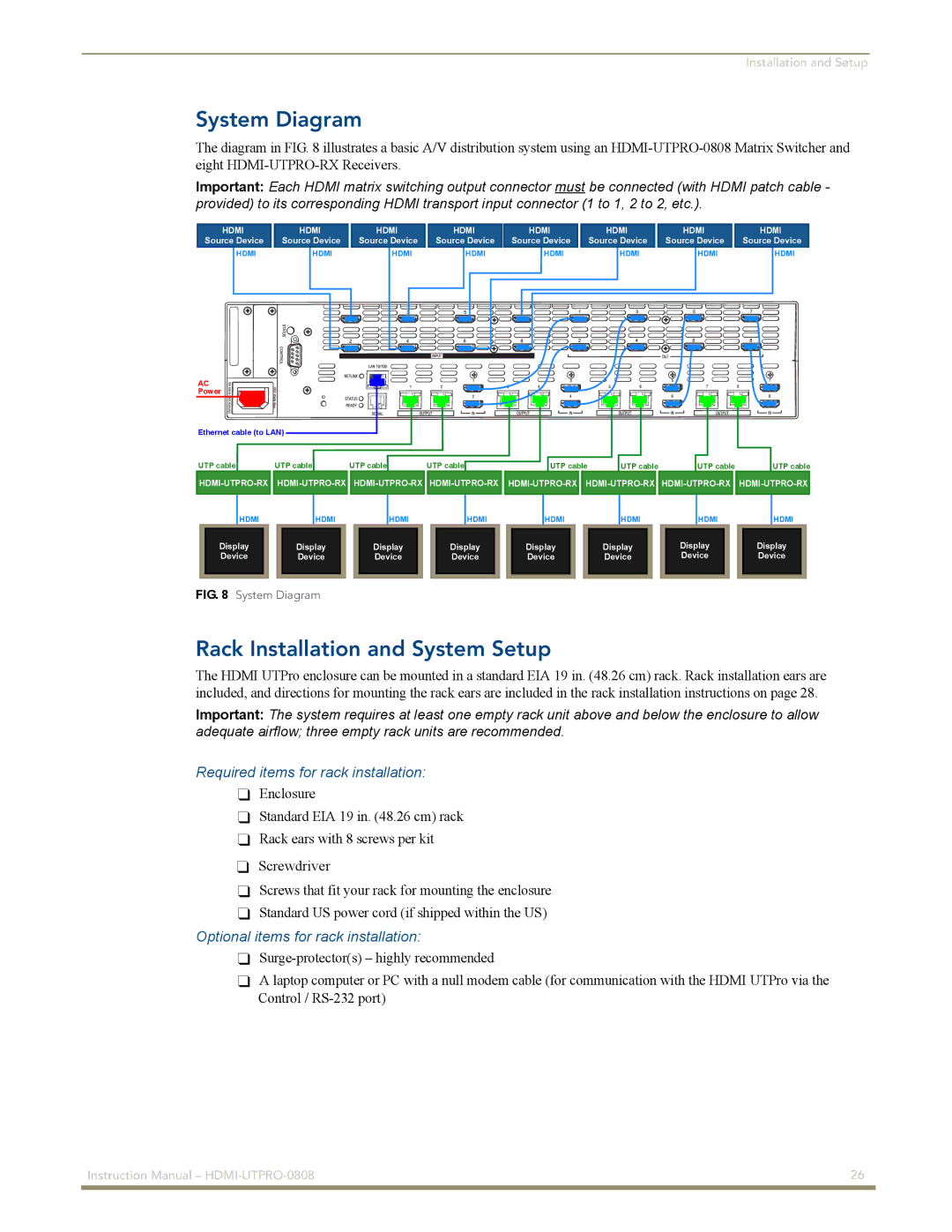
The diagram in FIG. 8 illustrates a basic A/V distribution system using an
Important: Each HDMI matrix switching output connector must be connected (with HDMI patch cable - provided) to its corresponding HDMI transport input connector (1 to 1, 2 to 2, etc.).
HDMI |
| HDMI | ||||
Source Device |
| Source Device | ||||
| HDMI |
|
| HDMI | ||
|
|
|
|
|
|
|
|
|
|
|
|
|
|
|
|
|
|
|
|
|
AC
Power
HDMI |
| HDMI |
| HDMI |
| HDMI |
Source Device |
| Source Device |
| Source Device |
| Source Device |
HDMI | HDMI | HDMI | HDMI |
HDMI
Source Device
HDMI
HDMI
Source Device
HDMI
Ethernet cable (to LAN) |
|
|
|
|
|
| |
UTP cable | UTP cable | UTP cable | UTP cable | UTP cable | UTP cable | UTP cable | UTP cable |
![]()
![]()
![]()
![]()
![]()
![]() HDMI-UTPRO-RX
HDMI-UTPRO-RX![]()
![]()
![]()
![]()
![]()
![]()
![]()
![]()
HDMI | HDMI | HDMI | HDMI | HDMI | HDMI | HDMI | HDMI |
Display | Display | Display | Display | Display | Display | Display | Display |
Device | Device | Device | Device | Device | Device | Device | Device |
FIG. 8 System Diagram |
|
|
|
|
|
| |
Rack Installation and System Setup
The HDMI UTPro enclosure can be mounted in a standard EIA 19 in. (48.26 cm) rack. Rack installation ears are included, and directions for mounting the rack ears are included in the rack installation instructions on page 28.
Important: The system requires at least one empty rack unit above and below the enclosure to allow adequate airflow; three empty rack units are recommended.
Required items for rack installation:
Enclosure
Standard EIA 19 in. (48.26 cm) rack Rack ears with 8 screws per kit
Screwdriver
Screws that fit your rack for mounting the enclosure
Standard US power cord (if shipped within the US)
Optional items for rack installation:
A laptop computer or PC with a null modem cable (for communication with the HDMI UTPro via the Control /
Instruction Manual – | 26 |
|
|
