Installation and Setup
Establishing an Ethernet 10/100 Network Connection
The LAN 10/100
Ethernet Pinouts and Signals |
|
|
|
|
| |
Pin | Signals | Connections | Pairing | Color | ||
1 | TX+ | 1 | 1 | 1 | 2 | White / Orange |
2 | TX- | 2 | 2 |
|
| Orange |
3 | RX+ | 3 | 3 | 3 | 6 | White / Green |
4 | no connection | 4 | 4 |
|
| Blue |
5 | no connection | 5 | 5 |
|
| White / Blue |
6 | RX- | 6 | 6 |
|
| Green |
7 | no connection | 7 | 7 |
|
| White / Brown |
8 | no connection | 8 | 8 |
|
| Brown |
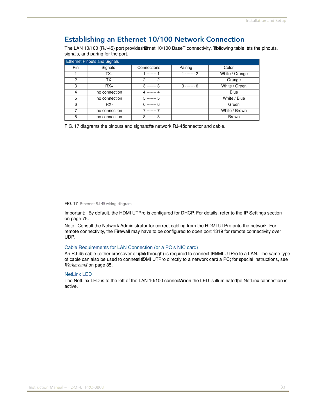
FIG. 17 diagrams the pinouts and signals for the network RJ-45 connector and cable.
FIG. 17 Ethernet RJ-45 wiring diagram
Important: By default, the HDMI UTPro is configured for DHCP. For details, refer to the IP Settings section on page 75.
Note: Consult the Network Administrator for correct cabling from the HDMI UTPro onto the network. For remote connectivity, the Firewall may have to be configured to open port 1319 for remote connectivity over UDP.
Cable Requirements for LAN Connection (or a PC’s NIC card)
An
NetLinx LED
The NetLinx LED is to the left of the LAN 10/100 connector. When the LED is illuminated, the NetLinx connection is active.
Instruction Manual – | 33 |
|
|