Appendix B – Programmer’s Interface for System Diagnostics
Appendix B – Programmer’s Interface for System Diagnostics
System Component Information
The HDMI UTPro displays system information in its splash screen* for diagnostic purposes. The information indicates the current status and
~scr! ![]()
[1:Enclosure] AutoPatch
[5:VM Configuration] count = 3
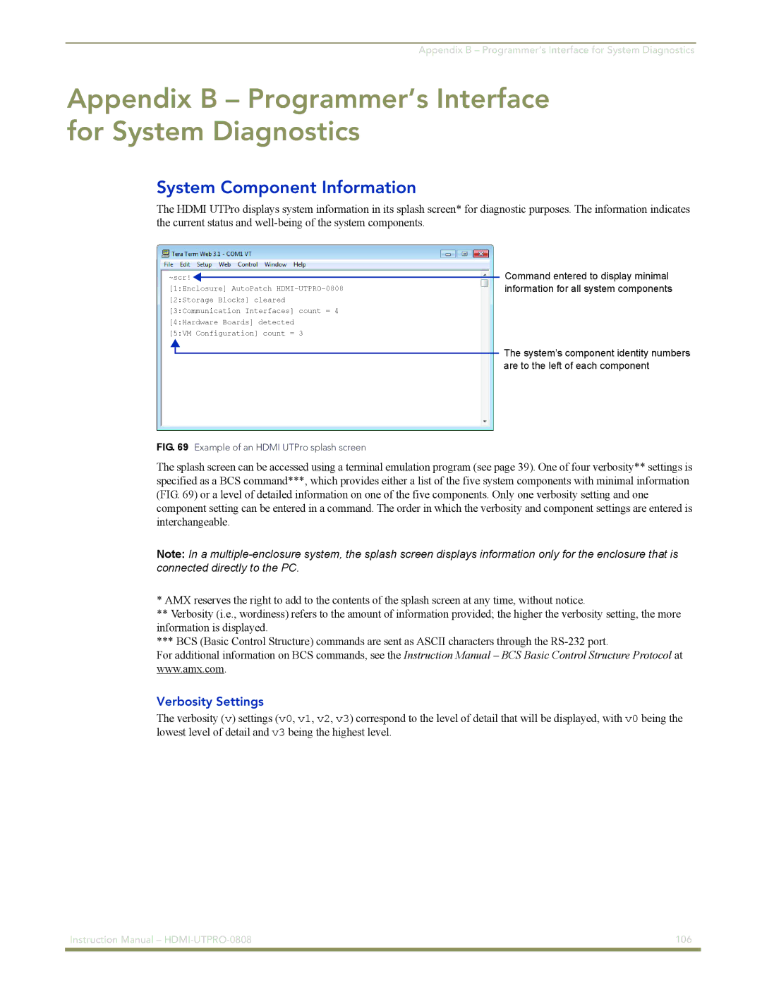
FIG. 69 Example of an HDMI UTPro splash screen
Command entered to display minimal information for all system components
The system’s component identity numbers are to the left of each component
The splash screen can be accessed using a terminal emulation program (see page 39). One of four verbosity** settings is specified as a BCS command***, which provides either a list of the five system components with minimal information (FIG. 69) or a level of detailed information on one of the five components. Only one verbosity setting and one component setting can be entered in a command. The order in which the verbosity and component settings are entered is interchangeable.
Note: In a
*AMX reserves the right to add to the contents of the splash screen at any time, without notice.
**Verbosity (i.e., wordiness) refers to the amount of information provided; the higher the verbosity setting, the more information is displayed.
***BCS (Basic Control Structure) commands are sent as ASCII characters through the
For additional information on BCS commands, see the Instruction Manual – BCS Basic Control Structure Protocol at www.amx.com.
Verbosity Settings
The verbosity (v) settings (v0, v1, v2, v3) correspond to the level of detail that will be displayed, with v0 being the lowest level of detail and v3 being the highest level.
Instruction Manual – | 106 |
|
|