List of Figures
Figure A-1:
Figure A-2:
Figure A-3:
Figure A-4:
Figure A-5:
Figure B-1:
Figure B-2:
Figure B-3: Figure B-4:
Figure B-5:
Figure B-6: Figure B-7:
Figure B-8: Figure B-9:
Figure B-10:
Figure B-11:
Figure B-12:
Figure B-13: Figure B-14:
Figure C-1: Figure C-2:
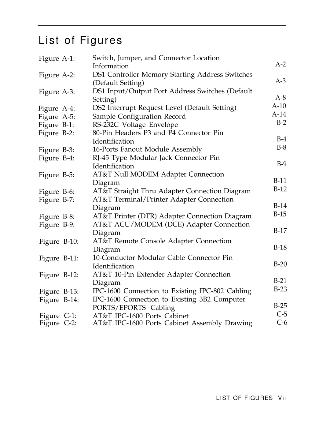
Switch, Jumper, and Connector Location Information
DS1 Controller Memory Starting Address Switches (Default Setting)
DS1 Input/Output Port Address Switches (Default Setting)
DS2 Interrupt Request Level (Default Setting) Sample Configuration Record
RS-232C Voltage Envelope
80-Pin Headers P3 and P4 Connector Pin Identification
16-Ports Fanout Module Assembly
RJ-45 Type Modular Jack Connector Pin
Identification
AT&T Null MODEM Adapter Connection Diagram
AT&T Straight Thru Adapter Connection Diagram
AT&T Terminal/Printer Adapter Connection
Diagram
AT&T Printer (DTR) Adapter Connection Diagram
AT&T ACU/MODEM (DCE) Adapter Connection
Diagram
AT&T Remote Console Adapter Connection Diagram
10-Conductor Modular Cable Connector Pin Identification
AT&T 10-Pin Extender Adapter Connection Diagram
IPC-1600 Connection to Existing IPC-802 Cabling IPC-1600 Connection to Existing 3B2 Computer PORTS/EPORTS Cabling
AT&T IPC-1600 Ports Cabinet
AT&T IPC-1600 Ports Cabinet Assembly Drawing
LIST OF FIGURES Vii
