66
SmartStack STS-LM Connectors and LEDs
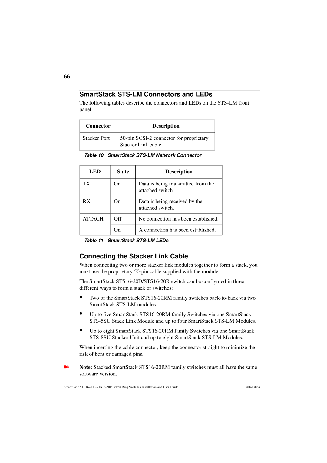
The following tables describe the connectors and LEDs on the
Connector |
|
| Description |
|
|
|
|
|
|
|
|
|
|
|
Stacker Port |
|
| ||
|
| Stacker Link cable. |
| |
|
|
|
|
|
|
|
|
| |
Table 10. SmartStack | ||||
|
|
|
| |
LED |
| State | Description | |
|
|
| ||
|
|
| ||
TX | On | Data is being transmitted from the | ||
|
|
| attached switch. | |
|
|
| ||
RX | On | Data is being received by the | ||
|
|
| attached switch. | |
|
|
| ||
ATTACH | Off | No connection has been established. | ||
|
|
| ||
| On | A connection has been established. | ||
|
|
|
|
|
|
|
|
|
|
Table 11. SmartStack
Connecting the Stacker Link Cable
When connecting two or more stacker link modules together to form a stack, you must use the proprietary
The SmartStack
•
•
•
Two of the SmartStack
Up to five SmartStack
Up to eight SmartStack
When inserting the cable connector, keep the connector straight to minimize the risk of bent or damaged pins.
➽Note: Stacked SmartStack
SmartStack | Installation |