34
BRF |
|
Bridge No. B1 |
|
Backup BRF |
|
Inactive |
|
A | A |
T | T |
M | M |
BRF |
|
|
Bridge No. B2 |
|
|
Backup BRF |
|
|
Bridge No. B1 |
|
|
Active | A | A |
| ||
| T | T |
| M | M |
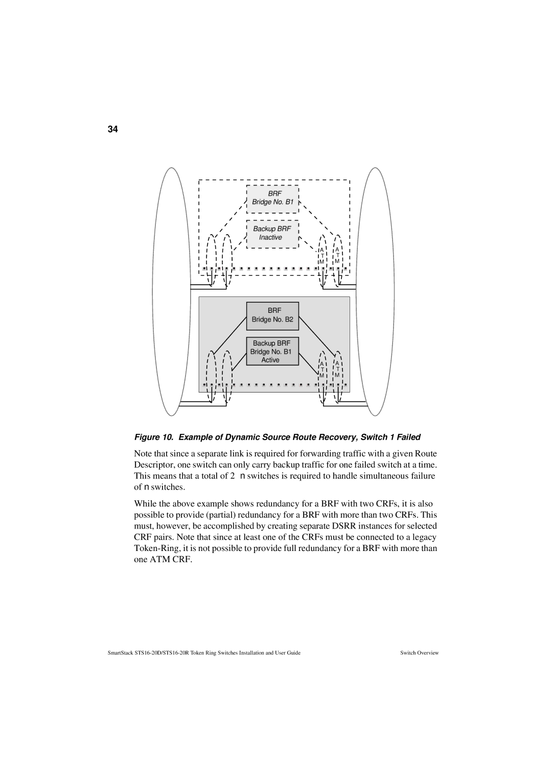
Figure 10. Example of Dynamic Source Route Recovery, Switch 1 Failed
Note that since a separate link is required for forwarding traffic with a given Route Descriptor, one switch can only carry backup traffic for one failed switch at a time. This means that a total of 2⋅ n switches is required to handle simultaneous failure of n switches.
While the above example shows redundancy for a BRF with two CRFs, it is also possible to provide (partial) redundancy for a BRF with more than two CRFs. This must, however, be accomplished by creating separate DSRR instances for selected CRF pairs. Note that since at least one of the CRFs must be connected to a legacy
SmartStack | Switch Overview |
