21
Multiple Bridging Modes
The SmartStack
|
| BRF 1 |
|
CRF 1 | CRF 2 | CRF 3 | CRF 4 |
|
|
| Switch |
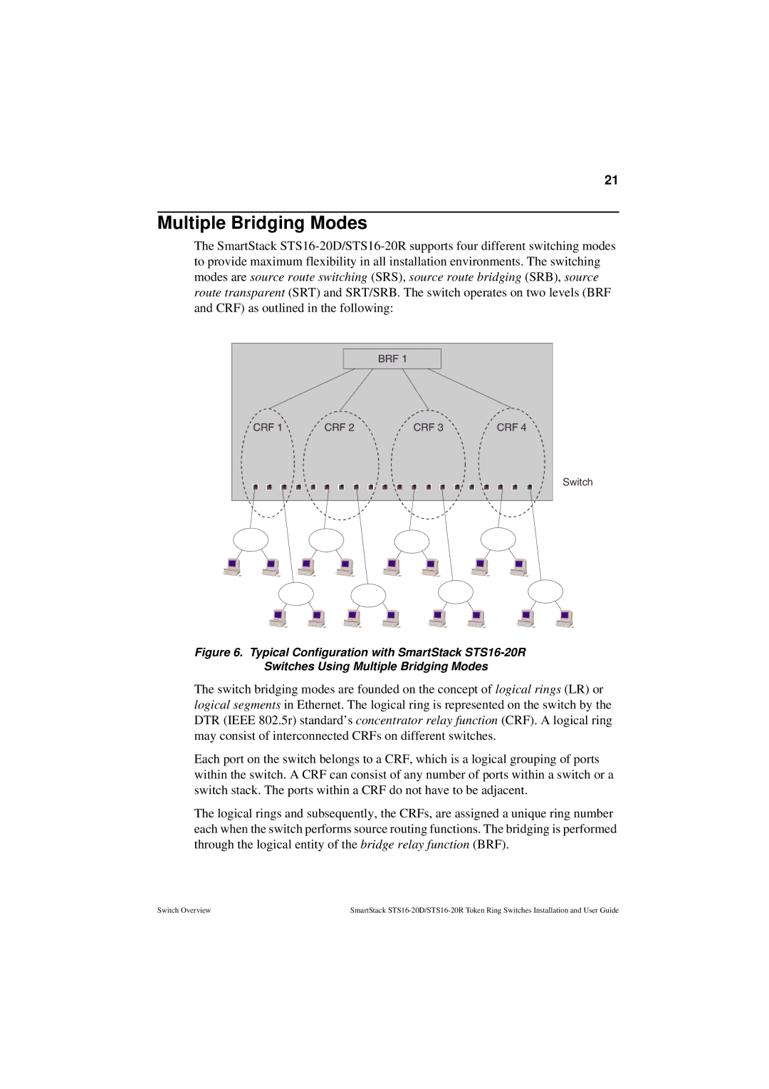
Figure 6. Typical Configuration with SmartStack STS16-20R
Switches Using Multiple Bridging Modes
The switch bridging modes are founded on the concept of logical rings (LR) or logical segments in Ethernet. The logical ring is represented on the switch by the DTR (IEEE 802.5r) standard’s concentrator relay function (CRF). A logical ring may consist of interconnected CRFs on different switches.
Each port on the switch belongs to a CRF, which is a logical grouping of ports within the switch. A CRF can consist of any number of ports within a switch or a switch stack. The ports within a CRF do not have to be adjacent.
The logical rings and subsequently, the CRFs, are assigned a unique ring number each when the switch performs source routing functions. The bridging is performed through the logical entity of the bridge relay function (BRF).
Switch Overview | SmartStack |